Общий каталог Dijet 2018 - страница 419
Навигация
 Общий каталог Dijet 2012 на русском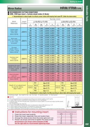
Tooling by DIJET Indexable Tools Mirror Radius HRM / FRMTyPE ■ RECOMMENDED CUTTING CONDITIONS ● HRM, FRM type insert + Carbide shank holder (C-Body) ※ Recommended to reduce depth of cut ap by corner radius with keeping feed speed Vf. (Refer the below table) Tool dia. (mm) Work Insert φ16×R3/φ17×R3 φ20×R3/φ22×R3 Materials Grades ℓ ae ap n -1 Vf ℓ ae ap n -1 Vf (mm) (mm) (mm) (min ) (mm/min) (mm) (mm) (mm) (min ) (mm/min) Carbon steel 35 7.0 0.60 3,800 4,500 40 9.8 0.60 3,000 3,600 S50C, S55C 80 7.0 0.60 3,800 3,800 100 9.8 0.60 3,000 3,000 (C50, C55) JC8015 120 7.0 0.40 3,800 3,800 150 9.8 0.40 3,000 3,000 Below 250HB 160 7.0 0.30 3,800 3,800 200 9.8 0.30 3,000 3,000 Mold steel 35 7.0 0.60 3,500 4,200 40 9.8 0.60 2,800 3,300 HPM7, PX5, NAK80, P20 80 7.0 0.60 3,500 3,500 100 9.8 0.60 2,800 2,800 (1.2311, P20) JC8015 120 7.0 0.40 3,500 3,500 150 9.8 0.40 2,800 2,800 30-43HRC 160 7.0 0.30 3,500 3,500 200 9.8 0.30 2,800 2,800 Die steel 35 7.0 0.60 3,500 4,200 40 9.8 0.60 2,800 3,300 SKD61, SKD11 80 7.0 0.60 3,500 3,500 100 9.8 0.60 2,800 2,800 (1.2344, 1.2379) JC8015 120 7.0 0.40 3,500 3,500 150 9.8 0.40 2,800 2,800 Below 255HB 160 7.0 0.30 3,500 3,500 200 9.8 0.30 2,800 2,800 35 7.0 0.60 3,400 4,000 40 9.8 0.60 2,700 3,200 Stainless steel 80 7.0 0.60 3,400 3,400 100 9.8 0.60 2,700 2,700 SUS304 JC8015 Below 250HB 120 7.0 0.40 3,400 3,400 150 9.8 0.40 2,700 2,700 160 7.0 0.30 3,400 3,400 200 9.8 0.30 2,700 2,700 Hardened die steel 35 7.0 0.30 3,000 3,600 40 9.8 0.30 2,400 2,800 SKD61, DAC, DHA 80 7.0 0.30 3,000 3,000 100 9.8 0.30 2,400 2,400 (1.2344, 1.2379) JC8015 120 7.0 0.25 3,000 3,000 150 9.8 0.25 2,400 2,400 40-50HRC 160 7.0 0.20 3,000 3,000 200 9.8 0.20 2,400 2,400 Grey & Nodular 35 7.0 0.60 3,200 3,800 40 9.8 0.60 2,500 3,000 cast iron 80 7.0 0.60 3,200 3,200 100 9.8 0.60 2,500 2,500 FC, FCD (GG, GGG) JC8015 120 7.0 0.40 3,200 3,200 150 9.8 0.40 2,500 2,500 Below 300HB 160 7.0 0.30 3,200 3,200 200 9.8 0.30 2,500 2,500 R1 ap×0.50 R1 ap×0.50 Depth of cut adjustment Corner R1.5 ap×0.60 Corner R1.5 ap×0.60 by corner radius radius R2 radius R2 (ap × ratio) ap×0.75 ap×0.75 R3 ap×1.0 R3 ap×1.0 ※ Recommend to reduce depth of cut ap according to above table with keeping feed speed ℓ: Overhung length, ap: Depth of cut, ae: Pick feed, n: Spindle speed, Vf: Feed speed ■ NOTE 1) The cutting parameters to be adjusted according to the machine rigidity or work rigidity. 2) In case chatter occurrs, recommend to reduce depth of cut or feed speed. 3) If machine does not have enough power, recommend to reduce depth of cut first and reduce spindle speed and feed speed. 4) Use air blow to flush the chips out. 5) In case of 50-55HRC (Hardened die steel), recommend to reduce 30% above ap, n, Vf. 6) In case of good surface requirement, recommend to reduce feed speed. 7) In case of ramping, ramping angle up to 2° 30′is recommended. 8) In case of slotting with overhung length exceeding 5 x Dc, recommend to reduce depth of cut and feed speed. ★ Instructions for mounting insert Dimensions (mm) Recommended torque 1. Clean the insert seat carefully. φDc (N・m) 6 0.5 2. Clean the insert, especially hole and location face. 8 0.9 3. Change the clamp screw when the screw gets worn out. 10 1.2 4. Please use torque wrenches to tighten the clamp screw. 12 2.0 Recommend to use Torque control wrenches (C180) 16 3.0 See the right table for recommended tightening torque. 20 4.0 C207