Общий каталог Dijet 2018 - страница 306
Навигация
 Общий каталог Dijet 2012 на русском
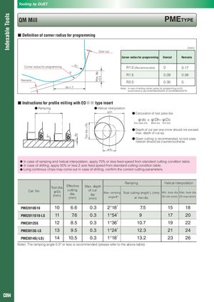
Indexable Tools θ° ap Tool dia.φDc Max. ap =0.4 Tooling by DIJET QM Mill PMETyPE ■ Definition of corner radius for programming (mm) Over cut Corner radius for programming Overcut Remains Corner radius for programming R1 R1.0 (Recommended) 0 0.17 R R1.5 0.09 0.08 Remains R2.0 0.30 0 W=1.7 Note) In case of setting corner radius for programming to R2, recommend to use EOMT060220ZER or EOHW060220ZTR. ■ Instructions for profile milling with EO※※ type insert ● Ramping ● Helical interpolation L φDh ● Calculation of tool pass dia. φdc = φDh−φDc Tool pass dia. Bore dia. Tool dia. ● Depth of cut per one circle should not exceed max. depth of cut ap. ● Down cutting is recommended, so tool pass rotation should be counterclockwise. φdc ● In case of ramping and helical interpolation, apply 70% or less feed speed from standard cutting condition table. ● In case of drilling, apply 50% or less Z axis feed speed from standard cutting condition table. ● Long continous chips may come out in case of drilling, confirm the correct cutting parameters. Ramping Helical interpolation Cat. No. Tool dia. EffectiveφDc(mm)cuttingdia.(mm)Max. depthof cutapMax. rampingTotal cutting length L (mm) Min. bore dia. Max. bore dia.(mm)angleθ°at max.apDh min (mm)Dh max (mm) PME2010S10 10 6.6 0.3 2°18′ 7.5 15 18 PME2011S10-LS 11 7.6 0.3 1°54′ 9 17 20 PME30125S 12 8.5 0.3 1°36′ 10.7 19 22 PME3013S-LS 13 9.5 0.3 1°24′ 12.3 21 24 PME3014S(-LS) 14 10.5 0.3 1°18′ 13.2 23 26 Note) The ramping angle 0.5° or less is recommended (please refer to the above table). C094