Общий каталог Dijet 2018 - страница 296
Навигация
 Общий каталог Dijet 2012 на русском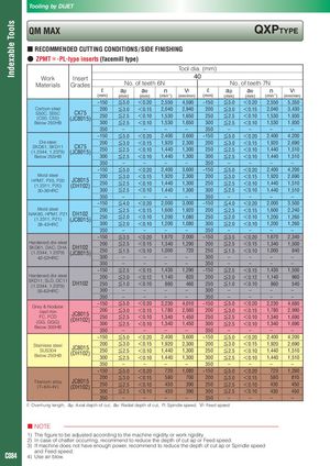
Tooling by DIJET Indexable Tools QM MAX QXPTyPE ■ RECOMMENDED CUTTING CONDITIONS / SIDE FINISHING ● ZPMT*-PL-type inserts (facemill type) Tool dia. (mm) Work Insert 40 Materials Grades No. of teeth 6N No. of teeth 7N ℓ ap ae n -1 Vf ℓ ap ae n Vf (mm) (mm) (mm) (min ) (mm/min) (mm) (mm) (mm) (min-1) (mm/min) ~150 ≦5.0 <0.20 2,550 4,590 ~150 ≦5.0 <0.20 2,550 5,350 Carbon steel 200 ≦3.0 <0.15 2,040 2,940 200 ≦3.0 <0.15 2,040 3,430 S50C, S55C CX75 250 ≦2.5 <0.10 1,530 1,650 250 ≦2.5 <0.10 1,530 1,930 (C50, C55) (JC8015) Below 250HB 300 ≦2.5 <0.10 1,530 1,650 300 ≦2.5 <0.10 1,530 1,930 350 – – – – 350 – – – – ~150 ≦5.0 <0.20 2,400 3,600 ~150 ≦5.0 <0.20 2,400 4,200 Die steel 200 ≦3.0 <0.15 1,920 2,300 200 ≦3.0 <0.15 1,920 2,690 SKD61, SKD11 CX75 250 ≦2.5 <0.10 1,440 1,300 250 ≦2.5 <0.10 1,440 1,510 (1.2344, 1.2379) (JC8015) Below 255HB 300 ≦2.5 <0.10 1,440 1,300 300 ≦2.5 <0.10 1,440 1,510 350 – – – – 350 – – – – ~150 ≦5.0 <0.20 2,400 3,600 ~150 ≦5.0 <0.20 2,400 4,200 Mold steel 200 ≦3.0 <0.15 1,920 2,300 200 ≦3.0 <0.15 1,920 2,690 HPM7, PX5, P20 JC8015 250 ≦2.5 <0.10 1,440 1,300 250 ≦2.5 <0.10 1,440 1,510 (1.2311, P20) (DH102) 30-36HRC 300 ≦2.5 <0.10 1,440 1,300 300 ≦2.5 <0.10 1,440 1,510 350 – – – – 350 – – – – ~150 ≦4.0 <0.20 2,000 3,000 ~150 ≦4.0 <0.20 2,000 3,500 Mold steel 200 ≦2.5 <0.15 1,600 1,920 200 ≦2.5 <0.15 1,600 2,240 NAK80, HPM1, P21 DH102 250 ≦2.0 <0.10 1,200 1,080 250 ≦2.0 <0.10 1,200 1,260 (1.2311, P21) (JC8015) 38-43HRC 300 ≦2.0 <0.10 1,200 1,080 300 ≦2.0 <0.10 1,200 1,260 350 – – – – 350 – – – – ~150 ≦3.5 <0.20 1,670 2,000 ~150 ≦3.5 <0.20 1,670 2,340 Hardened die steel 200 ≦2.5 <0.15 1,340 1,290 200 ≦2.5 <0.15 1,340 1,500 SKD61, DAC, DHA DH102 (1.2344, 1.2379) (JC8015) 250 ≦1.5 <0.10 1,000 720 250 ≦1.5 <0.10 1,000 840 42-52HRC 300 – – – – 300 – – – – 350 – – – – 350 – – – – ~150 ≦2.5 <0.15 1,430 1,290 ~150 ≦2.5 <0.15 1,430 1,500 Hardened die steel 200 ≦2.0 <0.12 1,140 820 200 ≦2.0 <0.12 1,140 960 SKD11, SLD, DC11 (1.2344, 1.2379) DH102 250 ≦1.0 <0.10 860 460 250 ≦1.0 <0.10 860 540 55-62HRC 300 – – – – 300 – – – – 350 – – – – 350 – – – – ~150 ≦5.0 <0.20 2,230 4,010 ~150 ≦5.0 <0.20 2,230 4,680 Grey & Nodular cast iron 200 ≦3.0 <0.15 1,780 2,560 200 ≦3.0 <0.15 1,780 2,990 JC8015 FC, FCD 250 ≦2.5 <0.10 1,340 1,450 250 ≦2.5 <0.10 1,340 1,690 (GG, GGG) (DH102) 300 ≦2.5 <0.10 1,340 1,450 300 ≦2.5 <0.10 1,340 1,690 Below 300HB 350 – – – – 350 – – – – ~150 ≦5.0 <0.20 2,400 3,600 ~150 ≦5.0 <0.20 2,400 4,200 Stainless steel 200 ≦3.0 <0.15 1,920 2,300 200 ≦3.0 <0.15 1,920 2,690 JC8015 SUS304 250 ≦2.5 <0.10 1,440 1,300 250 ≦2.5 <0.10 1,440 1,510 Below 250HB (DH102) 300 ≦2.5 <0.10 1,440 1,300 300 ≦2.5 <0.10 1,440 1,510 350 – – – – 350 – – – – ~150 ≦5.0 <0.20 720 1,080 ~150 ≦5.0 <0.20 720 1,260 200 ≦3.0 <0.15 580 700 200 ≦3.0 <0.15 580 810 Titanium alloy JC8015 250 ≦2.5 <0.10 430 390 250 ≦2.5 <0.10 430 450 (Ti-6Al-4V) (DH102) 300 ≦2.5 <0.10 430 390 300 ≦2.5 <0.10 430 450 350 – – – – 350 – – – – ℓ: Overhung length, ap: Axial depth of cut, ae: Radial depth of cut, n: Spindle speed, Vf: Feed speed ■ NOTE 1) The figure to be adjusted according to the machine rigidity or work rigidity. 2) In case of chatter occurring, recommend to reduce the depth of cut ap or Feed speed. 3) If machine does not have enough power, recommend to reduce the depth of cut ap or Spindle speed and Feed speed. C084 4) Use air blow.