Общий каталог Dijet 2018 - страница 271
Навигация
 Общий каталог Dijet 2012 на русском
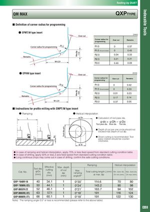
Indexable Tools Tooling by DIJET QM MAX QXPTyPE ■ Definition of corner radius for programming ● EPMT/W type insert (mm) Corner radius for Over cut Remains programming R1.0 0 0.57 R1.5 (Recommended) 0 0.45 R2.0 0.04 0.33 R2.5 0.21 0.21 R3.0 0.40 0.09 ● EPHW type insert (mm) Corner radius for Over cut Remains programming R1.0 0 0.42 R1.5 (Recommended) 0 0.33 R2.0 0.01 0.23 R2.5 0.17 0.14 R3.0 0.37 0.05 ■ Instructions for profile milling with EMPT/W type insert ● Ramping ● Helical interpolation ● Calculation of tool pass dia. φdc = φDh – φDc Tool pass dia. Bore dia. Tool dia. ● Depth of cut per one circle should exceed max.depth of cut ap. not ● Down cutting is recommended. Tool pass rotation should be counter- clockwise. ● In case of ramping and helical interpolation, apply 70% or less feed speed from standard cutting condition table. ● In case of drilling, apply 50% or less Z axis feed speed from standard cutting condition table. ● Long continous chips may come out in case of drilling, confirm the safe cutting conditions. Ramping Helical interpolation Cat. No. EffectiveTool dia.cuttingφDcdia.(mm)(mm)Max. depthof cutap(mm)Max.rampingangleθ°Total cutting length L (mm)Min. bore dia.Max. bore dia.at max. apDh min (mm)Dh max (mm) QXP-*040R-16 40 34.1 1 0°30′ 114.6 70 80 QXP-*050R(-22) 50 44.1 1 0°24′ 143.2 90 98 QXP-8052R-22 52 46.1 1 0°21′ 163.7 94 102 QXP-8063R(-22) 63 57.1 1 0°18′ 191 116 124 QXP-8066R(-27) 66 60.1 1 0°18′ 191 122 130 Note) The ramping angle 0.5° or less is recommended (please refer to the above table). C059