Общий каталог Dijet 2018 - страница 242
Навигация
 Общий каталог Dijet 2012 на русском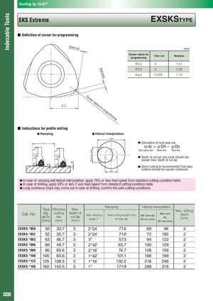
Tooling by DIJET Indexable Tools SKS Extreme EXSKSTyPE ■ Definition of corner for programming Over c ut (mm) Corner radius for Over cut Remains programming R3.0 0 1.41 R3.5 0 1.30 R em R4.0 0.025 1.19 ains Co rn er rad ius 8.2 for pr og ram mi ng ■ Instructions for profile milling ● Ramping ● Helical interpolation φDh L ● Calculation of tool pass dia. φdc = φDh – φDc Tool pass dia. Bore dia. Tool dia. Tool dia.φDc ● Depth of cut per one circle should not exceed max. depth of cut ap. ap 8° ● Down cutting is recommended.Tool pass φdc rotation should be counter-clockwise. ● In case of ramping and helical interpolation, apply 70% or less feed speed from standard cutting condition table. ● In case of drilling, apply 50% or less Z axis feed speed from standard cutting condition table. ● Long continous chips may come out in case of drilling, confirm the safe cutting conditions. Ramping Helical interpolation Tool Effective Max. Max. drilling Cat. No. dia. cutting depth of Max.ramping Total cutting length L(m) Max. bore depth Min. bore dia. φDc dia. cut ap angleθ° at max. ap dia. (mm) Dh min (mm) (mm) (mm) (mm) Dh max (mm) EXSKS-*050 50 33.7 3 2°24′ 71.6 68 96 2 EXSKS-*052 52 35.7 3 2°24′ 71.6 72 100 2 EXSKS-*063 63 46.7 3 3° 57.3 94 122 2 EXSKS-*066 66 49.7 3 2°42′ 63.7 100 128 2 EXSKS-*080 80 63.6 3 2°18′ 74.7 128 156 2 EXSKS-*100 100 83.6 3 1°42′ 101.1 168 196 2 EXSKS-*125 125 108.5 3 1°18′ 132.2 218 246 2 EXSKS-*160 160 143.5 3 1° 171.9 288 316 2 C030