Общий каталог Dijet 2018 - страница 153
Навигация
 Общий каталог Dijet 2012 на русском
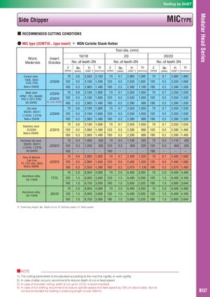
Modular Head Series Tooling by DIJET Side Chipper MICTYPE ■ RECOMMENDED CUTTING CONDITIONS ● MIC type (ZCMT10...type insert) + MSN Carbide Shank Holder Tool dia. (mm) 16/18 20 20/22 Work Insert Materials Grades No. of teeth 2N No. of teeth 2N No. of teeth 3N ℓ ap n Vf ℓ ap n Vf ℓ ap n Vf (mm) (mm) (min-1) (mm/min) (mm) (mm) (min-1) (mm/min) (mm) (mm) (min-1) (mm/min) Carbon steel 70 0.6 3,580 2,150 70 0.7 2,860 1,300 70 0.7 2,860 1,860 S50C, S55C(C50, C55)JC5040 120 0.5 3,180 1,590 120 0.5 2,550 1,300 120 0.5 2,550 1,660 Below 250HB 160 0.3 2,980 1,490 190 0.2 2,390 1,100 190 0.2 2,390 1,550 Mold steel JC5040 70 0.6 3,180 1,600 70 0.7 2,550 1,050 70 0.7 2,550 1,530 HPM7, PX5, NAK80,P20 (1.2311,P20)JC5015120 0.5 3,180 1,600 120 0.5 2,550 1,050 120 0.5 2,550 1,530 30-43HRC For over 40HRC 160 0.3 2,980 1,490 190 0.2 2,390 990 190 0.2 2,390 1,530 Die steel 70 0.6 3,180 1,600 70 0.7 2,550 1,050 70 0.7 2,550 1,530 SKD61, SKD11(1.2344, 1.2379)JC5040 120 0.5 3,180 1,600 120 0.5 2,550 1,050 120 0.5 2,550 1,530 Below 255HB 160 0.3 2,980 1,490 190 0.2 2,390 990 190 0.2 2,390 1,530 Stainless steel 70 0.6 3,180 1,600 70 0.7 2,550 1,050 70 0.7 2,550 1,530 SUS304 JC5015 120 0.5 2,980 1,490 120 0.5 2,390 990 120 0.5 2,390 1,400 Below 250HB 160 0.3 2,980 1,490 190 0.2 2,390 990 190 0.2 2,390 1,400 Hardened die steel 70 0.4 1,400 350 70 0.5 1,100 255 70 0.5 1,110 420 SKD61, SKD11(1.2344, 1.2379)JC5015 120 0.3 1,200 300 120 0.3 950 220 120 0.3 950 330 40-50HRC 160 – – – 190 – – – 190 – – – Grey & Nodular 70 0.6 2,980 1,800 70 0.7 2,400 1,320 70 0.7 2,400 1,680 cast ironFC, FCD (GG, GGG)JC5015 120 0.5 2,980 1,650 120 0.5 2,400 1,320 120 0.5 2,400 1,580 Below 300HB 160 0.3 2,500 1,380 190 0.2 2,070 1,130 190 0.2 2,070 1,400 70 2.0 8,000 4,000 70 2.0 6,400 3,200 70 2.0 6,400 4,480 Aluminium alloy50-110HBFZ15 120 1.5 8,000 3,600 120 1.5 6,400 3,200 120 1.5 6,400 4,160 160 1.0 6,700 3,000 190 1.0 5,600 2,520 190 1.0 5,600 3,640 70 2.0 8,000 4,000 70 2.0 6,400 3,200 70 2.0 6,400 4,480 Aluminium alloy50-110HBJDA10 120 1.5 8,000 3,600 120 1.5 6,400 3,200 120 1.5 6,400 4,160 160 1.0 6,700 3,000 190 1.0 5,600 2,520 190 1.0 5,600 3,640 ℓ: Overhung length, ap: Depth of cut, n: Spindle speed, Vf: Feed speed ■NOTE 1) The cutting parameters to be adjusted according to the machine rigidity or work rigidity. 2) In case chatter occurrs, recommend to reduce depth of cut or feed speed. 3) In case of shoulder milling, width of cut up to 1/2 Dc is recommended. 4) In case of full slotting, recommend to reduce spindle speed and feed speed by 70% on above table. But donot recommended full slotting if overhung length is over 150mm.B137