Tooling by DIJET
QM MAX MQTTYPE
MQT
TyPE
Definition of flute shape for
programming
MQT
TyPE
Recommended cutting conditions for
MQT
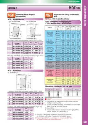
MQT-...A03/A05 Holder MQT Type + MSN Carbide Shank holder
Fig.1 XPHW/T Type Fig.2 YPHW Type Basic parameter of cutting conditions
Maximum inc
lination angl
eθ°
Inclination angleθ° : XPHT/W Type
L/D ~3.5 3.5~ 5 5 ~ 6.5 6.5~
Work
Vc 1 x0.75 x 0.6 x0.5
ap (mm) ≦1.5 ≦1.2 ≦1.2 ≦1.0
Carbon steel
<0.12 <0.10 <0.10 <0.10
Ra
S50C, S55C ae (mm)
Rh
R0
.8 R0.3~R0.8 (C50, C55) Vc (m/min) 600 450 360 300
3.0
Below 250HB
fz (mm/t) 0.2 0.2 0.2 0.2
φDc(Intersection of Ra) φDc(Interection withθ°)
ap (mm) ≦1.5 ≦1.2 ≦1.2 ≦1.0
Die steel
° Accuracy of tool dia. with master inserts −0.02~−0.05
SKD61, SKD11 ae (mm) <0.12 <0.10 <0.10 <0.10
Dc Ra Rh Inclination (1.2344,1.2379) Vc (m/min) 500 375 300 250
Fig. Cat No. (mm) (mm) (mm) angle Below 255HB
fz (mm/t) 0.2 0.2 0.2 0.2
1 MQT-2016A03-M8 φ15.5 R64.19 8.76 1˚~6˚ a p (mm) ≦1.2 ≦1.0 ≦1.0 ≦0.8
Mold steel
1 MQT-2016A05-M8 φ15.5 R64.34 10.98 3˚~8˚ HPM7, PX5, P20 ae (mm) <0.12 <0.10 <0.10 <0.10
(1.2311, P20)
1 MQT-2020A03-M10 φ19.5 R63.34 8.67 1˚~6˚ Vc (m/min) 450 337 270 225
30~36HRC
1 MQT-2020A05-M10 φ19.5 R63.46 10.85 3˚~8˚ fz (mm/t) 0.2 0.2 0.2 0.2
a p (mm) ≦1.0 ≦0.8 ≦0.8 ≦0.6
Mold steel
<0.12 <0.10 <0.10 <0.10
° Tool dia. with YPHW Type inserts (Inclination angle: 3°、5°)
NAK80, HPM1, P21 ae (mm)
Dc Inclination (1.2311,P21) Vc (m/min) 400 300 240 200
Fig. Cat No. (mm) angle 38~43HRC
fz (mm/t) 0.2 0.2 0.2 0.2
2 MQT-2016A03-M8 φ16 3˚
Hardened ap (mm) ≦1.0 ≦0.8 ≦0.8 ≦0.6
2 MQT-2016A05-M8 φ16 5˚ die steel ae (mm) <0.10 <0.08 <0.08 <0.08
SKD61, DAC, DHA
2 MQT-2020A03-M10 φ20 3˚ (1.2344,1.2379) Vc (m/min) 250 187 150 125
2 MQT-2020A05-M10 φ20 5˚ 42~52HRC fz (mm/t) 0.15 0.15 0.15 0.15
MQT-…A00 Holder Grey & Nodular ap (mm) ≦1.5 ≦1.2 ≦1.2 ≦1.0
Fig. 3 XPHW/Type
cast iron ae (mm) <0.12 <0.10 <0.10 <0.10
FC, FCD
Maximum inclination ang (GG,GGG) Vc (m/min) 600 450 360 300
leθ°
Below 300HB fz (mm/t) 0.25 0.25 0.25 0.25
ap (mm) ≦1.2 ≦1.0 ≦1.0 ≦0.8
Stainless steel ae (mm) <0.12 <0.10 <0.10 <0.10
SUS304
Below 250HB Vc (m/min) 500 375 300 250
fz (mm/t) 0.2 0.2 0.2 0.2
9
Ra
Rh (Ra)
R0
.8 Theoretical cusp height: XPHT/W Type
φDc Cusp height (μm) ap(mm) Cusp height (μm) ap(mm)
° Accuracy of tool dia. with master inserts −0.02~−0.05 0.50 0.5 2.40 1.1
0.71 0.6 2.86 1.2
Dc Ra Rh Inclination
0.97 0.7 3.35 1.3
Fig. Cat No. (mm) (mm) (mm) angle
1.27
1.61
0.8
0.9
3.89
4.46
1.4
1.5
3 MQT-2016A00-M8 φ16 R63.27 5.48 0˚~3˚ 1.98 1.0
3 MQT-4020A00-M10 φ20 R64.29 5.48 0˚~3˚ ■ NOTE
3 MQT-5025A00-M12 φ25 R63.26 5.48 0˚~3˚ 1) The figure to be adjusted according to the machine
rigidity or work regidity.
3 MQT-6035A00-M16 φ35 R62.16 5.48 0˚~3˚ 2) In case of chatter occurring, recommend to reduce the
° Tool dia. with YPHW Type inserts (Inclination angle: 0°) depth of cut ap and Pick feed ae.
3) Use air blow.
Dc Inclination
Fig. Cat No. (mm) angle 4) In case carbon steel or die steel machining by CX75
inserts, reduce 80% above Vc, fz.
– MQT-2016A00-M8 φ16 0˚
– MQT-4020A00-M10 φ20 0˚ 1) Shape of cutting edge is different depends on combinati-
– MQT-5025A00-M12 φ25 on of inserts and holder. Please refer to the table above.
0˚
2) Regarding detail of the tool shape we will provide DXF file
– MQT-6035A00-M16 φ35 0˚ so please contact our closest distributor.
B087
 Общий каталог Dijet 2012 на русском