Общий каталог D'andrea 2022 - страница 120
Навигация
 Общий каталог D'ANDREA 2018
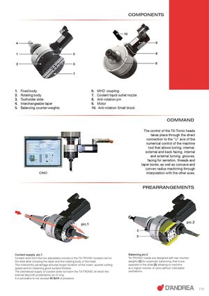
COMPONENTS 10 4 9 1 5 8 2 3 6 7 1. Fixed body 6. MHD’ coupling 2. Rotating body 7. Coolant liquid outlet nozzle 3. Toolholder slide 8. Anti-rotation pin 4. Interchangeable taper 9. Motor 5. Balancing counter-weights 10. Anti-rotation Small block COMMAND The control of the TA-Tronic heads takes place through the direct connection to the “U” axis of the numerical control of the machine tool that allows boring, internal, external and back facing, internal and external turning, grooves, facing for serration, threads and taper bores, as well as concave and convex radius machining through CNC interpolation with the other axes. PREARRANGEMENTS pic.1 pic.2 5 3 Coolant supply pic.1 Balancing pic.2 Coolant exits from the two adjustable nozzles in the TA-TRONIC located next to TA-TRONIC heads are designed with two counter- the slide after crossing the taper and the rotating body of the head. weights (5) for automatic balancing, that move This noteworthy advantage ensures longer duration of the insert, quicker cutting opposite to the slide (3) allowing to machine speed and for obtaining good surface finishes. at a higher number of rpms without noticeable The centralized supply of coolant does not harm the TA-TRONIC of which the oscillations. internal labyrinth protected by an O-ring. It is advisable to not exceed 40 BAR of pressure. 119