Общий каталог D'andrea 2022 - страница 102
Навигация
 Общий каталог D'ANDREA 2018
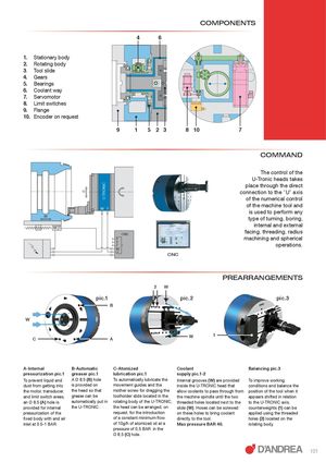
U TRONIC U TM W TM W COMPONENTS 4 6 1. Stationary body 2. Rotating body 3. Tool slide 4. Gears 5. Bearings 6. Coolant way 7. Servomotor 8. Limit switches 9. Flange 10. Encoder on request 9 1 5 2 3 8 10 7 COMMAND The control of the U-Tronic heads takes place through the direct connection to the "U" axis of the numerical control of the machine tool and is used to perform any type of turning, boring, internal and external CNC facing, threading, radius X machining and spherical YZ operations. W U CNC PREARRANGEMENTS 2 W pic.1 pic.2 pic.3 B W 1 C A A-Internal B-Automatic C-Atomized Coolant Balancing pic.3 pressurization pic.1 greaser pic.1 lubrication pic.1 supply pic.1-2 To prevent liquid and A Ø 8,5 (B) hole To automatically lubricate the Internal grooves (W) are provided To improve working dust from getting into is provided on movement guides and the inside the U-TRONIC head that conditions and balance the the motor, transducer, the head so that mother screw for dragging the allow coolants to pass through from position of the tool when it and limit switch areas, grease can be toolholder slide located in the the machine spindle until the two appears shifted in relation an Ø 8,5 (A) hole is automatically put in rotating body of the U-TRONIC, threaded holes located next to the to the U-TRONIC axis, provided for internal the U-TRONIC. the head can be arranged, on slide (W). Hoses can be screwed counterweights (1) can be pressurization of the request, for the introduction on these holes to bring coolant applied using the threaded fixed body with and air of a constant minimum flow directly to the tool. holes (2) located on the inlet at 0.5-1 BAR. of 10g/h of atomized oil at a Max pressure BAR 40. rotating body. pressure of 0,5 BAR in the Ø 8,5 (C) hole. 101