Каталог ZCC-CT оснастка - страница 94
Навигация
 Каталог ZCC-CT токарная обработка
 Каталог ZCC-CT сверла монолитные
 Каталог ZCC-CT расточные системы
 Каталог ZCC-CT фрезы монолитные
 Каталог ZCC-CT фрезы со сменными пластинами
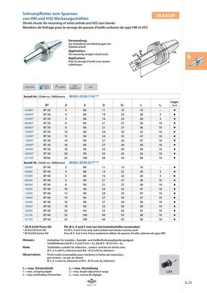
Schrump utter zum Spannenvon HM und HSS Werkzeugschäften JIS B 6339 Shrink chucks for mounting of solid carbide and HSS-tool shanks Mandrins de frettage pour le serrage de queues d‘outils carbures de type HM et HSS Verwendung: Zur Aufnahme von Werkzeugen mit Zylinderschaft. Application: For mounting straight-shank tools.Application: b Pour le serrage d’outils avec queue cylindrique. JIS B 6339 FormAD/B ≤ 0,003 G6,315.000 min-1CAD Bestell-Nr. / Order no. / Référence 90501.0330.17A*** Lager BT d A D D1 l1 l2 Stock 03080* BT 30 3 80 11 15 10 – 04080* BT 30 4 80 14 22 20 5 05080* BT 30 5 80 16 22 20 5 06080* BT 30 6 80 21 27 36 10 08080* BT 30 8 80 21 27 36 10 10090* BT 30 10 90 24 32 42 10 12090* BT 30 12 90 24 32 47 10 14090* BT 30 14 90 27 34 47 10 16090* BT 30 16 90 27 34 50 10 18090* BT 30 18 90 33 42 50 10 20090* BT 30 20 90 33 42 52 10 25100* BT30 25 100 44 53 58 10 Bestell-Nr. / Order no. / Référence 90501.0340.017*** 03080 BT 40 3 80 11 15 10 – 04080 BT 40 4 80 14 22 20 5 05080 BT 40 5 80 16 22 20 5 06090 BT 40 6 90 21 27 36 10 08090 BT 40 8 90 21 27 36 10 10090 BT 40 10 90 24 32 41 10 12090 BT 40 12 90 24 32 47 10 14090 BT 40 14 90 27 34 47 10 16090 BT 40 16 90 27 34 50 10 18090 BT 40 18 90 33 42 50 10 20090 BT 40 20 90 33 42 52 10 25100 BT 40 25 100 44 53 58 10 32100 BT 40 32 100 44 53 58 10 * JIS B 6339 Form AD Für Ø 3, 4 und 5 mm nur Hartmetallschäfte verwenden! * JIS B 6339 form AD For Ø 3, 4 and 5 mm only solid carbide tool shanks must be used! * JIS B 6339 forme AD Pour Ø 3, 4 et 5 mm il faut seulement utiliser de queues d‘outils carbures de type HM! Hinweis: Aufnahme für Induktiv-, Kontakt- und Heißluftschrumpfgeräte geeignet. Schafttoleranz bei Ø 3, 4 und 5 mm = h4, bei Ø 6 – Ø 32 mm = h6 Note: Toolholders suitable for induction-, contact- and hot air shrink units. Ø 3, 4, 5 with h4-tolerance and Ø 6 – Ø 32 with h6-tolerance Observation: Porte-outils convenables pour machines à fretter par induction-, par contact-, ou par air chaud. Ø 3, 4, 5 avec h4-tolerance et Ø 6 – Ø 32 avec h6-tolerance l1 = max. Einstecktiefe l2 = max. Verstellweg l1 = max. clamping depth l2 = max. length adjustment range i.51 l1 = max. profondeur d’insertion l2 = max. course de réglage b.25