Каталог Tungaloy инструмент для автоматов швейцарского типа - страница 290
Навигация

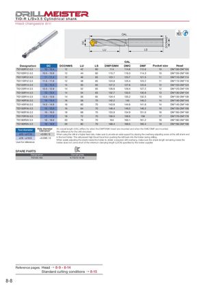
DC DCONMSh6 TID-R L/D=3.5 Cylindrical shank Head-changeable drill OAL LU LS OAL Designation DC DCONMS LU LS DMP/DMH DMC DMF Pocket size Head TID100R12-3.5 10 - 10.4 12 42 60 114 114.6 112.6 10 DM*100-DM*104 TID105R12-3.5 10.5 - 10.9 12 44 60 115.7 116.3 114.3 10 DM*105-DM*109 TID110R12-3.5 11 - 11.4 12 46 65 123.1 123.7 121.5 11 DM*110-DM*114 TID115R12-3.5 11.5 - 11.9 12 48 65 124.8 125.4 123.2 11 DM*115-DM*119 TID120R14-3.5 12 - 12.4 14 50 65 127.2 127.8 125.6 12 DM*120-DM*124 TID125R14-3.5 12.5 - 12.9 14 52 65 128.8 129.4 127.2 12 DM*125-DM*129 TID130R14-3.5 13 - 13.4 14 54 65 132.7 133.5 130.8 13 DM*130-DM*134 TID135R14-3.5 13.5 - 13.9 14 56 65 134.4 135.2 132.5 13 DM*135-DM*139 TID140R16-3.5 14 - 14.4 16 58 70 142.2 143 140.2 14 DM*140-DM*144 TID145R16-3.5 14.5 - 14.9 16 60 70 143.8 144.6 141.8 14 DM*145-DM*149 TID150R16-3.5 15 - 15.9 16 64 70 148.4 149.3 146.3 15 DM*150-DM*159 TID160R18-3.5 16 - 16.9 18 68 70 153.9 154.9 151.6 16 DM*160-DM*169 TID170R18-3.5 17 - 17.9 18 72 70 158.5 159.5 156 17 DM*170-DM*179 TID180R20-3.5 18 - 18.9 20 76 70 164 165.1 161.2 18 DM*180-DM*189 TID190R20-3.5 19 - 19.9 20 80 70 168.4 169.5 165.4 19 DM*190-DM*199 Tool diameter Hole diametertolerance*An overall length (OAL) differs for when the DMP/DMH insert are mounted and when the DMC/DMF are mounted.(No difference for the drill shoulder) ø10 - ø17.9 +0.08 / 0 When using the drill at a higher feed rate, make sure to provide an axial support by placing the overhang adjusting screw at the drill shank end ø18 - ø19.9 +0.095 / 0 in the tool holder. This will prevent high thrust force from pushing the drill back into the holder during drilling. When axially adjusting the shank inside the holder to obtain a required drill overhang, make sure the shank length remaining inside the *Just for reference holder does not come short of the minimum clamping length (LSCN) specified by the holder supplier. SPARE PARTS Designation Clamping key TID100-190 K-TID10-19.99 Reference pages: Head → 8-9 - 8-14 Standard cutting conditions → 8-15 8-8
 Общий каталог Tungaloy 2020 - 2021
 Каталог Tungaloy глубокое сверление 2
 Каталог Tungaloy зубофрезерование
 Брошюра Tungaloy новая продукция
 Каталог Tungaloy глубокое сверление 1