Каталог TooTool техническая информация 1 - страница 40
Навигация
 Общий каталог TooTool
 Каталог TooTool монолитные фрезы
 Каталог TooTool техническая информация 2
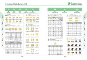
Turning Insert Code System (ISO) A\ GM \ 8f Insert Shape Relief Angle Tolerance Cross Section Type Cutting Edge Length,Diameter of Inscribed Circle Height of Cutting Edge Nose Radius (Nose R) Chip Breaker for Turning v Insert Shape amis Relief Angle Cutting Edge Length, Diameter of Inscribed Circle Height of Cutting EdgeQEjOBiaGlGIlGMEJE3GMf¥lrarafEinm- GM <(8 ^0 > ^ ^< 55 > A 55’ / Symbol Tm70A®icIncht t ti Metric d(mm )Specialtype03I04I03I0603-I02I1.2(5 )l3.97 t 7 t 04 I 05 I 04 I 08 I 04 08 I S3 I 1.5(6 ) l 4.76 O 05 I 06 I 05 I 09 I 05 09 I 03 I 1.8(7 )! 5.56 Symbol Height of Cutting Edge(t )066.00MetricInchmm Inch © Tolerance Cross Section Type 06 I 07 I 06 I 11 06 I 11 I 04 I 2 I 6.35 01 1(2) 1.59 1/1608|09|07|1307|13|05|2.5I7.94GM088.00TO1.1251.799/12 809I11I09I16I09I16I063I 9.52 5T11.21.985/64 10 10.00 02 1.5 (3) 2. 38 3/32 d : Inscribed circle /Y-t: ThicknessjT\m : Refer to figure(VJ L>. \ / \XZ7 11 I 13 I 11 I 19 I 11 I 19 I 07 I 3.5 I 11.11 T2 1.75 2. 78 7/641212.0012I15I12I2212I22I08I4I 12.700323.181/814I17I14I2414I24I09I4.5I1429T32.53.975/32 d d C’Sink 70° ~ 90° C’Sink 70° - 90° 16 I 19 I 15 I 27 15 I 27 I 10 I 5 115.87 5 04 3 4.76 3/16 16 16.00 05 3.5 5. 56 7/32 (mm) A B C 17 I 21 I 17 I 30 17 I 30 I 11 5.5 I 17.46 06 4 6.35 1/4 Class d m tA± 0.025± 0.005± 0.025 19 I 23 I 19 I 33 19 I 33 I 13 6 I 19.052020.00 07 5 7.94 5/16 C ± 0.025 ± 0.013 ± 0025 22 I 27 I 22 I 38 I 22 I 38 I 15 7 I 22.22 5 09 6 9. 52 3/8 H ± 0.013 ± 0.013 ± 0.025E± 0.025± 0.025±0 025 \ 7 25 25.00 11 7 11.11 7/1625I3125I44I25I44I178I25.4012812.701/2 GJ*K*L*M*N*u* ±±±±±± ±0,025 - 0 05 ±0.15 - 005 ±0.15 - 0 05 ±0.15 - 0.05 ±0.15 - 005 ±0.15 - 008 ±0.25 ± 0.025± 0.005± 0.013± 0.025±0.08 ±0 08 ±0.13 --- ±0.20 ±0.18 ±0.38±0.13±0 025± 0025± 0.025± 0.13±0 025±0.13 C’Sink 70° - 90°FGH 32 I 38 I 31 I 54 I 31 I 54 I 21 10 I 31.75III3232.00 ( ) Symbol for small size insert()Symbol forsmallsizeinsertChip Breaker for T urningNose Radius (Nose R)aoEjaoQaoaGM * Sides are based on unground insertToleran ce on C,E,H ,M,0,P,R,S,T ,W Insert Shape (Except ionalcase)C’Sink 70° - 90°UIZ7\ / d Toleran ce on dJ,KL, M, N U Toleran ce on mM, N U J M N 6.35 ± 0.05 ± 0.08 ± 008 l ± 0.13 9.52 5 ± 0.05 ± 0.08 ± 008 ± 01312.7± 0.08± 0.13± 0.13I± 02015 87 5± 0.10± 0.18± 015±0 2719 ,05± 0.10± 0.18±0.15l± 0.2725.4± 0.13± 0.25± 018± 038\ZZ7CZ7C’Sink 40° - 60°C’Sink 40° ~ 60°Symbol Corner RadiusMetricInchMetricInch0100.10.004 £7 KR ^ZR ^MA Q R TToleran ce on D Insert Shape (Except ionalcase)dToleran ce on dToleran ce on m635± 0.05± 0.11Specialtype9.52 5± 0.05± 0.1112.7± 0.08± 01515 87 5± 0.10± 018_1C’Sink 40° - 60°C’Sink 40° - 60°020.50.20.0080410.41/640820.81/321231.23/641641.61/162052.05/64HA^HS^TM^HF2462.43/322872.87/64V 19.05 ± 0.10 ± 018 U W X 32 8 3.2 1/8 00 Roundinsert (Inch) M0 Roundinsert (Metric ) HM HR AL SL 079 080