Каталог TooTool техническая информация 1 - страница 13
Навигация
 Общий каталог TooTool
 Каталог TooTool монолитные фрезы
 Каталог TooTool техническая информация 2
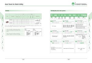
Auto Tools for Multi Utility A\ Inserts Turning tiny tool code system Size Coated Shape Designation W ±0.03 Dmax re H T d 0* 8§ LDr\j3 ConfigurationQ__ TT 060 T R 15 150 ISO - 2 TTIM451}2f\3f4f56\7\8f\9fMain codeInsert sizeType ofHand ofMax .ProcessThreadCutting edgeCarbide Grades operation Insert Depth Figure Profile TKFS12R/L 100-S 1.00 6 0.05 8.7 2.2 4.4 0° 150-S 1.50 9 0.05 8.7 2.2 4.4 0° MX *200-S2.00120.058.72.24.40°/ Main Code Insert Size Type of operationiijfilgq o TKFS16R/L 150-S 1.50 14 0.05 9.5 2.2 4.4 0°200-S2.00160.059.52.24.40° x o> B = Boring BP=Profiling & Boring *As Fig. 1shows, cutting diameter of Insert indicates the cutting diameter when the top of the cutting edge is programmed to run 1mmbeyond center. Lead angle ( 0 ) shows the angle when installed in toolholder. TT = Tiny Tool 010: 1.0mm 015: 1.5mm 020: 2.0mm030: 3.0mm040: 4.0mm050: 5.0mm060: 6.0mm070: 7.0mm080: 8.0mmBB=Back BoringBF= ChamferingBU=FaceCutingBC=CopyingBW=Chamfering & ProfilingG=Square Grooving100: 10.0mm0XX: Special sizeGR=Round GroovingGF=Face Grooving GRF=Round Face Grooving T=Threading TD=Threading Relief GV= Deep Face Grooving As Fig.lshows, KTKFS is applicable when minimal Fig. 1 Fig. 2 clearance exists between the main spindle and sub Main Spindle Main Spindle'Short Distance Hand of Insert Max. Depth Process Figure spindle. Long DistanceSub SpindleSub Spindle KB 150 As Fig.2 shows, please use KTKFL when additional clearance is available. This will offer improve rigidity. Boring: Nose radius Grooving: Grooving width Threading: Partial profile: F60 R = Right hand styleL = Left hand style 05: 5.0mm 10: 10.0mm 15: 15.0mm A60 or A5520: 20.0mm25: 25.0mm30: 30.0mmAG60 orAg5535: 35.0mmFull profile:ISO MetricAmerican UN Tarpez DIN 103 ACME Thread Profile Cutting Edge Carbide Grades naa 0 TTIM45 ISO - ISO Metric UN - American UN (UNC, UNF, UNEF, UNS) None:Single ended 2:Double endedACME - ACME TTIP30 TTIM45 TTIS30 TR - Tarpez DIN103 N400 025 026