Общий каталог Sumitomo 2019 - 2020 - страница 53
Навигация
 Каталог Sumitomo запасные части
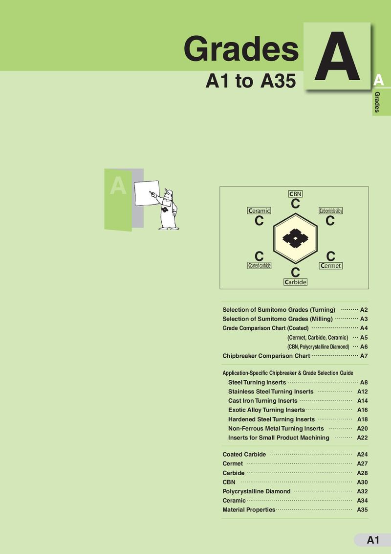 Каталог Sumitomo сплавы и режимы
 Техническая информация Sumitomo
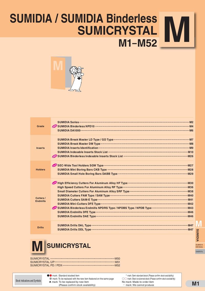 Каталог Sumitomo пластины с алмазными вставками Sumidia
 Каталог Sumitomo специальные торцевые фрезы
 Общий каталог Sumitomo 2018 - 2019
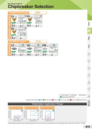
Finishing to Light CuttingCarburised Layer RemovalFinishing to Light CuttingDepth of Cut ap (mm) Depth of Cut ap (mm) Depth of Cut ap (mm) CeramicsSolid CBNPos.Neg.Insert By CutCCCtingDDD CRRRondSSSitioTTTnsVVV WWW C D R S T V WCDRSTVW Chipbreaker CCC DDD RRR SSS TTT VVV WWW C D R C D R Selection S T V W C D R S T V S T V W W pe AX EMAY SUMCCC IDDDBTOyRRRpeRSSS OTTTNVVVInWWWserCCt D R S T V WD CBN TyRpTeySpe T V W C D R S T V WAXType AY Type 2.500.05 LCCCV D R DDTypRRe SSDSPr3as0Mti2°cTTTa.l5lyK0impNVVVroveSdWWWchHip FCCV DDTypRRe0.05DSSPrasMticTTa2lKly.52im0N.VV15p5ro°SveWWdH C D R S T 2.V50 W30° 2.515° control in finishing of chip control in finishing hardened steel. of hardened steel. CCC DDD RRR 0SSS.05 TTT0.60VVV 3WWW0° CC DD RR S 0T.4 V WST45°VW C D R S T V W Break Master -35° Break Master 0C° 7D°CCDDRRR SSS TTT VVV WWW 0C° 7D° R S T V WCDRSTVW C D R S T V W ype SRVH CCC Type DDDTyRRRpeScSSSPoignntrifoMicl awTTTnitthlKycimarpbNVVVruorviseeSddcWWWlhaiyHper GFHB C D R S C D TRyTpyeSpe TT VV WW C RLHB D R S T TyTpyepe V W FB Typeremoval LB Type B 3.503° C D R 00..S3105CCDDRR -15SS°Break MasterTTT0.84VVV13WWW50°° C D R 3°S 0.T530.50V WCDRSTV2W0° C D R S 0.3T0 0.8V0 W 15°-15°15° 0.50 20° 0.80 15° 0° -35° C DCCDD(mm)RRRSSS TTT VVV WWW C D R S T V WCDRSTVW C D R S T V W 6 SUMIDIA CC DDep4th Dd of RCut R SS C epD2 R S InTTT sVVVerWWWt C D R S PT CV DWCDRSTVW C D R S T V W ype LLDDType CCCth D0DD PMK N S HRRR SSS TTT VVV WWW TypeF0Iadle.leo2eayldtbhraeRnakkasetrteofosr(pmfienc0imsia.hl4i/ncrguetotvifn)agluemdgineusmha0p.e6GGDD P C D TyTRpyepeISdeal M breakTerK N for meVdium S H finisWhing toCDRS T V W general machining of aluminum alloythanks to special cutting edge shapeDMLD C D TyRpeTyPSPperefMecTt K N S H breaVker fWorhigh-speed finishingof aluminum alloy 0.8 0.4 0.8 10.5.4 20° C D RCCBreak DDMasterRRSSSTTTVVV25°WWW C D R S T V 20W°CBreak DMasterRSTVW C D R S T V W25°Break Master 7° 11° NF-CCMT0602 ○○ Type 7° 11° NF-CCMT0602 ○○ Type 7° 11° NU-CCMT09T3 ○○ Type CCC DDD RRR SSS TTT VVV WWW C D R S T V WCDRSTVW C D (mm) R S T V W6Relief Angle7° Pos. C Dep4th of Cutd 11° Pos. CCC DDD RRR SSS TTT VVV WWW C D R S T V WCDRSTVW C ep D2 R S T V Wth0 0.2 0.4 0.6Feed Rate (mm/rev) D umpy Insert StandarCCd BDDreaRkRer SSHaTTndeVVd BWWreakeCr D R S T V W C D R S T V WBumpy InsertStandard BreakerHanded Breaker reak Master (CBNCC/PCDDD)RR SS TT VVFoWWr ChaCmfDeriBnRgreSak TMaVsteWr (CBCN/DPCRD) S T V FWor Chamfering R CC DD RR SS TT VV WW C D R S T V W C D R S T V W S CC DD RR SS TT VV WW C D R S T V W C D R S T V W C D R S T V W C D R S T V W C D R S T V W T C D R S T V W C D R S T V W C D R S T V W C D R S T V W C D R S T V W C D R S T V W V C D R S T V W Bumpy Chipbreaker Standard Chipbreaker Handed Chipbreaker Break Master (CBN/PCD) W Applicable Work Material: P Steel M Stainless Steel K Cast Iron N Non-Ferrous Metal S Exotic Alloy H Hardened Steel Chipbreaker Application Range SUMIBORON (For Hardened Steel)(Inscribed Circle up to 12.7mm) SUMIBORON (Carburised Layer Removal)(Inscribed Circle up to 12.7mm) SUMIDIA (For Aluminum Alloy) 0.7 H 0.7 H 2 N 0.5 0.5 SV Type GD Type 0.3 LV Type 0.3 1 FV Type 0.1 0.1 LD Type 0 0.1 0.2 0.3 0 0.1 0.2 0.3 0 0.1 0.2 0.3 0.4 Feed Rate f (mm/rev) Feed Rate f (mm/rev) Feed Rate f (mm/rev) Indicated chipbreaker application ranges and shapes are representative values only. Actual values may change according to the actual catalogue number. For details, refer to "Stock Items" in Chapter B. B15