Общий каталог Sumitomo 2018 - 2019 - страница 561
Навигация
- Pages 3-6_CS6_EN_web
- A 1-20 insert selection EN_web
- B 1-14 grades_EN_web
- C01-17 inserts intro pages_EN_web
- C18-56 negative inserts_EN_web
- C57-86 positive inserts_EN_web
- D 1-46 tool holders_EN_web
- E 1-24 boring bars_EN_web
- F 1-48 grooving_thread tools_EN_web
- G 1-54 milling cutters_EN_web
- H 1-48 insert type endmills_EN_web
- J 1-24 new endmills_EN_web
- J 25-50 endmills_EN_web
- K 1-46 Multi-Drills_EN_web
- K 47-76 Multi-Drills_EN_web
- L 1-28 cbn_pcd grades_EN_web
- M 1-34 cbn_pcd inserts_EN_web
- M 35-56 SHM tools_EN_web
- N1-24 technical guidance_EN_web
- P 1-8 spare parts_neu_EN_web
- P 9-22 index_notes_EN_web

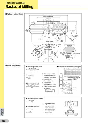
Technical Guidance Specific cutting force (N/mm2) doc Overall height Technical Guidance Basics of Milling Parts of a Milling Cutter External diameter of cutter body External diameter of boss Hole diameter Width of key way Cutter Body Depth of key way Axial rake angle Back locating Approach face Setting ring angle Front relief True rake Screw angle angle A Inclinationangle Insert Chip pocket Relief Diameter of cutter angle Locator Clamp Section A Setting ring Wiper flatclearance Major cutting edge angle Radial rake angle Inward dish(if trail angle)Chamfered corneror wiper flat (if 0°) Power Requirement l Calculating cutting force l Relation between feed rate, work material, specific cutting force Pc = doc . woc . v f . Kc605 1065η(kW) Work- –––s––– –– –– ––– 5––– – – l– –pieceAlloyCarbonCastAluminum No. steel steel iron alloy j 1.800 800 200 – k 1.400 600 160 – Pc : Net power requirement (kW) l 1.000 400 120 – l Horsepower H : Horsepower requirement (HP) Values in the table show the following properties: H= Pc0,75 Q : Chip removal amount (cm3/min) - Tensile strength (N/mm2) for alloy steel and carbon steelwoc : Cutting width (mm)- Hardness (HB) for cast iron vf : Feed speed (mm/min) doc : Depth of cut (mm) l Chip removal amount η : Machine efficiency (0,70 ~ 0,85) Q= doc 5 woc 5 v f (cm3/min) Kc : Specific cutting forrce (N/mm2) 1.000 Eg. rough value ( ) Steel : 2.500 ~ 3.000 Cast iron : 1.500 Feed rate (mm/tooth) l Calculating cutting speed vc = π 5D 5n 1.000 vc : Cutting speed (m/min) π ≈ 3,14 vf l Calculating feed rate D : Cutter diameter (mm)n:Rotation speed (rpm) vf = ft 5 z 5 n vf : Feed speed (mm/min) ft = vfz5n ft : Feed rate (mm/tooth)z:Number of teeth ft vf N6
 Общий каталог Sumitomo 2012
 Каталог Sumitomo резьбонарезной инструмент
 Каталог Sumitomo пластины с режущей кромкой-моноалмаз Sumicristal
 Каталог Sumitomo инструмент для обработки канавок
 Общий каталог Sumitomo 2019 - 2020
 Каталог Sumitomo запасные части