Общий каталог Sumitomo 2018 - 2019 - страница 322
Навигация
 Общий каталог Sumitomo 2012
 Каталог Sumitomo резьбонарезной инструмент
 Каталог Sumitomo пластины с режущей кромкой-моноалмаз Sumicristal
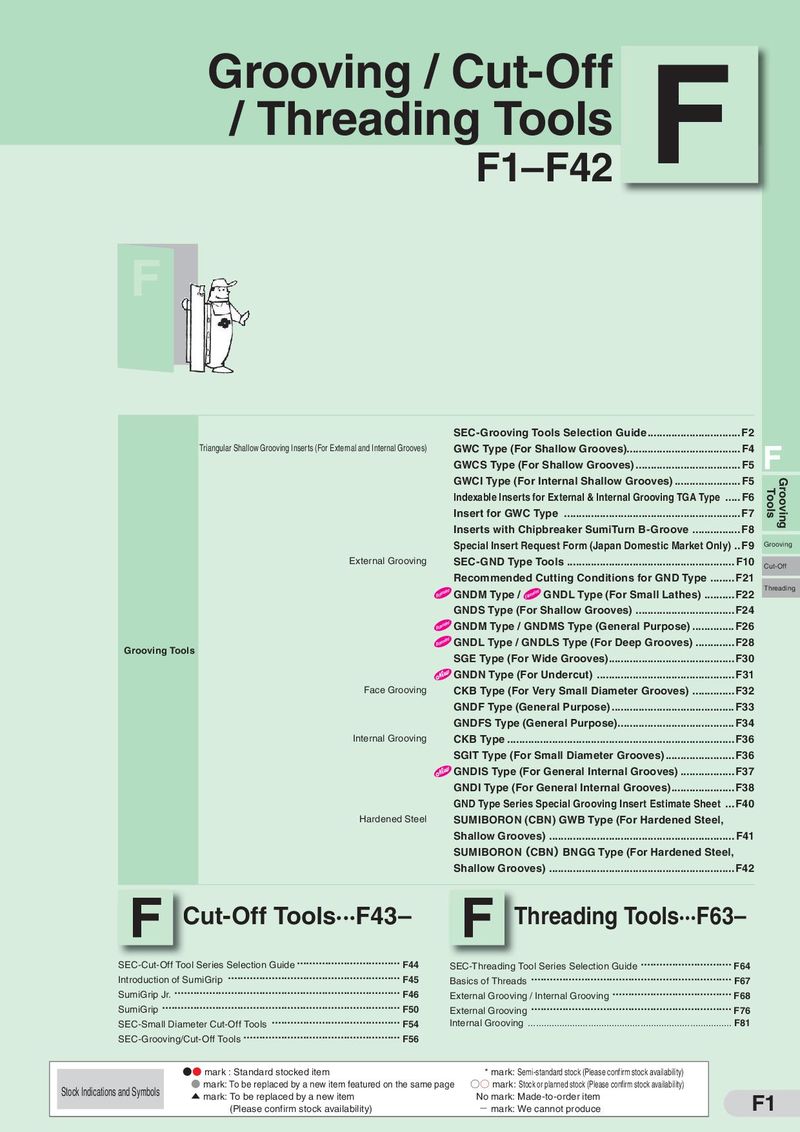 Каталог Sumitomo инструмент для обработки канавок
 Общий каталог Sumitomo 2019 - 2020
 Каталог Sumitomo запасные части
- Pages 3-6_CS6_EN_web
- A 1-20 insert selection EN_web
- B 1-14 grades_EN_web
- C01-17 inserts intro pages_EN_web
- C18-56 negative inserts_EN_web
- C57-86 positive inserts_EN_web
- D 1-46 tool holders_EN_web
- E 1-24 boring bars_EN_web
- F 1-48 grooving_thread tools_EN_web
- G 1-54 milling cutters_EN_web
- H 1-48 insert type endmills_EN_web
- J 1-24 new endmills_EN_web
- J 25-50 endmills_EN_web
- K 1-46 Multi-Drills_EN_web
- K 47-76 Multi-Drills_EN_web
- L 1-28 cbn_pcd grades_EN_web
- M 1-34 cbn_pcd inserts_EN_web
- M 35-56 SHM tools_EN_web
- N1-24 technical guidance_EN_web
- P 1-8 spare parts_neu_EN_web
- P 9-22 index_notes_EN_web
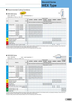
ChipbreakerChipbreaker Wavemill Series WEX Type Recommended Cutting Conditions 1,0mm WEX1000 Series New 4mm Cutter: WEX1012E Insert: AXMT060208PDER - Cutting Data: ap = 4mm, ae = 1mm, dry Coated Carbide „Diamond like Carbon“Coated Carbide ACP100 ACP200 ACP300 ACK200 ACK300 ACM200 ACM300 ISO Material HB Feed Rate (mm/tooth) 0,08 0,12 0,16 0,08 0,12 0,16 0,08 0,12 0,16 0,10 0,15 0,20 0,10 0,15 0,20 0,08 0,10 0,12 0,08 0,10 0,12 Cutting Speed vc (m/min) Unalloyed steel, <0, 15%C, annealed 125 G 280 240 220 240 220 200 220 200 180 „ , <0, 45%C, annealed 190 G 200 180 160 180 160 140 180 160 140 „ , <0, 45%C, tempered 250 G 180 120 140 160 140 120 150 130 110 „ , <0, 75%C, annealed 270 G 160 140 120 150 130 110 130 110 110 „ , <0, 75%C, tempered 300 G 100 80 70 90 70 60 70 60 50 P Low alloyed steel, annealed 180 G 200 180 160 180 160 150 160 150 130 „ , tempered 275 G 130 110 90 120 100 90 100 90 80 „ , tempered 300 G 120 100 80 100 90 80 90 80 60 „ , tempered 350 G 90 80 60 80 70 60 70 60 40 High alloyed and tool steel, annealed 200 G 180 170 160 170 160 130 150 140 120 „ , tempered 325 G 100 80 60 80 60 50 60 50 30 Stainless steel, ferritic/martensitic, annealed 200 E 175 150 120 140 130 110 M Martensitic, tempered 240 E 140 120 100 120 100 90 Austenitic, plunged 180 E 180 160 140 160 140 130 K Grey cast ironNodular cast iron GG 240 220 200 220 200 180160 140 120 140 120 100 S High tempered resist. alloys, Fe based, annealed E 50 35 45 25 The above recommended cutting conditions are meant as a guide. Actual conditions will depend on the individual machine, work shape and clamping. They will need to be adjusted according to machine rigidity, work clamp rigidity, cutting depth and other factors. For groove milling, reduce the feed rate approximately 70% of the corresponding value shown above. WEX2000 Series 12,5mm Cutter: WEX2025E Insert: AXMT123508PEER - 3mm Cutting Data: ap = 3mm, ae = 12,5mm, dry Coated Carbide „Diamond like Carbon“Coated Carbide ACP100 ACP200 ACP300 ACK200 ACK300 ACM200 ACM300 DL1000 ISO Material HB Feed Rate (mm/tooth) 0,08 0,15 0,20 0,08 0,15 0,20 0,08 0,15 0,20 0,08 0,15 0,20 0,08 0,15 0,20 0,08 0,15 0,20 0,08 0,15 0,20 0,05 0,15 0,22 Cutting Speed vc (m/min) Unalloyed steel, <0, 15%C, annealed 125 G 380 350 330 350 330 315 330 315 295 „ , <0, 45%C, annealed 190 G 285 255 235 255 235 220 235 220 220 „ , <0, 45%C, tempered 250 G 235 210 190 210 190 170 190 170 150 „ , <0, 75%C, annealed 270 G 190 162 143 171 152 133 152 133 115 „ , <0, 75%C, tempered 300 G 145 115 95 115 95 75 95 75 55 P Low alloyed steel, annealed 180 G 265 235 220 235 220 200 220 200 180 „ , tempered 275 G 170 145 125 150 130 115 130 115 95 „ , tempered 300 G 150 125 105 135 115 95 115 95 75 „ , tempered 350 G 125 95 75 105 85 65 85 65 45 High alloyed and tool steel, annealed 200 G 235 210 190 210 190 170 190 170 150 „ , tempered 325 G 125 95 75 95 75 55 75 55 35 Stainless steel, ferritic/martensitic, annealed 200 E 175 155 125 155 140 110 M Martensitic, tempered 240 EH 160 140 110 145 125 100 Austenitic, plunged 180 E 190 170 140 170 150 125 K Grey cast ironNodular cast iron GG 285 255 235 255 235 220190 160 140 160 140 125 S High tempered resist. alloys, Fe based, annealed 300 E„, hardened 330E 50 40 45 3535253020 Aluminium alloy, Si < 13% S 1000 750 500 N Aluminium alloy, Si > 13% S 250 200 170 Copper alloy S 350 330 300 The above recommended cutting conditions are meant as a guide. Actual conditions will depend on the individual machine, work shape and clamping. They will need to be adjusted according to machine rigidity, work clamp rigidity, cutting depth and other factors. For groove milling, reduce the feed rate approximately 70% of the corresponding value shown above. H25 Endmills Indexable