Общий каталог Sumitomo 2018 - 2019 - страница 248
Навигация
- Pages 3-6_CS6_EN_web
- A 1-20 insert selection EN_web
- B 1-14 grades_EN_web
- C01-17 inserts intro pages_EN_web
- C18-56 negative inserts_EN_web
- C57-86 positive inserts_EN_web
- D 1-46 tool holders_EN_web
- E 1-24 boring bars_EN_web
- F 1-48 grooving_thread tools_EN_web
- G 1-54 milling cutters_EN_web
- H 1-48 insert type endmills_EN_web
- J 1-24 new endmills_EN_web
- J 25-50 endmills_EN_web
- K 1-46 Multi-Drills_EN_web
- K 47-76 Multi-Drills_EN_web
- L 1-28 cbn_pcd grades_EN_web
- M 1-34 cbn_pcd inserts_EN_web
- M 35-56 SHM tools_EN_web
- N1-24 technical guidance_EN_web
- P 1-8 spare parts_neu_EN_web
- P 9-22 index_notes_EN_web

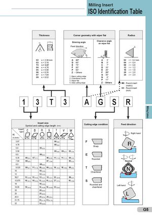
Milling Cutters Milling Insert ISO Identification Table Thickness Corner geometry with wiper flat Radius Entering angle Clearance angleon wiper flat Feed direction 1 4 3 2 02 s = 2,38 mm A 45° A 3° 02 r= 0,2 mm 03 s = 3,18 D 60° B 5° 04 r= 0,4 T3 s = 3,97 E 75° C 7° 08 r= 0,8 04 s = 4,76 F 85° D 15° 12 r= 1,2 05 s = 5,56 P 90° E 20° 16 r= 1,6 06 s = 6,35 Z - Others F 25° 20 r= 2,0 07 s = 7,9409s = 9,52 1. Major cutting edge2. Chamfered corner3. Wiper flatG30°N0°P11°24r= 2,4 4. Side cutting edge Z - Others M0 - Round insert (metric) 00 - Round insert (inch) 1 3 T 3 A G S R Insert sizeSymbolandcutting edgelength(mm) Cutting edge condition Feed direction Insert type IC Right hand d (mm) 3,97 06 (6,9) F 4,76 08 (8,2) Sharp 5,0 05 (5,0) 5,56 09 (9,6) 09 (9,7) 03 (3,8) 6,0 06 (6,0) E 6,35 06 (6,4) 07 (7,7) 06 (6,35) 11 (11,0) 11 (11,1) 04 (4,3) Rounded 7,94 08 (8,0) 07 (7,94) 05 (5,4) Neutral 8,0 08 (8,0) 9,525 09 (9,7) 11 (11,6) 09 (9,525) 09 (9,525) 16 (16,5) 16 (16,6) 06 (6,5) T 10 10 (10,0) Chamfered 12 12 (12,0) 12,7 12 (12,9) 15 (15,5) 12 (12,7) 12 (12,7) 22 (22,0) 08 (8,7) 15,875 16 (16,1) 19 (19,4) 15 (15,875) 15 (15,875) 27 (27,5) 10 (10,9) S 16 16 (16,0) Rounded and Left hand 19,05 19 (19,3) 19 (19,05) 19 (19,05) 33 (33,0) chamfered 20 20 (20,0) 25 25 (25,0) 25,4 25 (25,4) 25 (25,4) 31,75 31(31,75) 31(31,75) 32 32 (32,0) G5
 Общий каталог Sumitomo 2012
 Каталог Sumitomo резьбонарезной инструмент
 Каталог Sumitomo пластины с режущей кромкой-моноалмаз Sumicristal
 Каталог Sumitomo инструмент для обработки канавок
 Общий каталог Sumitomo 2019 - 2020
 Каталог Sumitomo запасные части