Общий каталог Sumitomo 2018 - 2019 - страница 247
Навигация
- Pages 3-6_CS6_EN_web
- A 1-20 insert selection EN_web
- B 1-14 grades_EN_web
- C01-17 inserts intro pages_EN_web
- C18-56 negative inserts_EN_web
- C57-86 positive inserts_EN_web
- D 1-46 tool holders_EN_web
- E 1-24 boring bars_EN_web
- F 1-48 grooving_thread tools_EN_web
- G 1-54 milling cutters_EN_web
- H 1-48 insert type endmills_EN_web
- J 1-24 new endmills_EN_web
- J 25-50 endmills_EN_web
- K 1-46 Multi-Drills_EN_web
- K 47-76 Multi-Drills_EN_web
- L 1-28 cbn_pcd grades_EN_web
- M 1-34 cbn_pcd inserts_EN_web
- M 35-56 SHM tools_EN_web
- N1-24 technical guidance_EN_web
- P 1-8 spare parts_neu_EN_web
- P 9-22 index_notes_EN_web

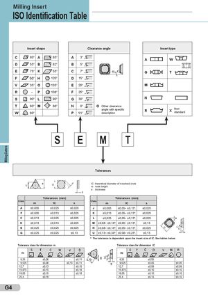
Milling Cutters Milling Insert ISO Identification Table Insert shape Clearance angle Insert type C 80° A 85° A 3° A W D 55° B 82° B 5° E 75° K 55° C 7° G T F 50° H 120° D 15° V 35° O 135° E 20° M R - P 108° F 25° S 90° L 90° G 30° N T 60° M 86° N 0° O Other clearance W 80° angle with specificP11°description R X Nonstandard S E M T Tolerances IC: theoretical diameter of inscribed circle m: nose height s: thickness Tolerances (mm) Tolerances (mm) Class m IC s Class m IC s A ±0,005 ±0,025 ±0,025 J ±0,005 ±0,05~ ±0,13*) ±0,025 F ±0,005 ±0,013 ±0,025 K ±0,013 ±0,05~ ±0,13*) ±0,025 C ±0,013 ±0,025 ±0,025 L ±0,025 ±0,05~ ±0,13*) ±0,025 H ±0,013 ±0,013 ±0,025 M ±0,08~ ±0,18*) ±0,05~ ±0,13*) ±0,13 E ±0,025 ±0,025 ±0,025 N ±0,08~ ±0,18*) ±0,05~ ±0,13*) ±0,025 G ±0,025 ±0,025 ±0,13 U ±0,13~ ±0,38*) ±0,08~ ±0,25*) ±0,13 *) The tolerance is dependent upon the insert size of IC. See tables below. Tolerance class for dimension m Tolerance class for dimension IC m IC 6,35 ±0,08 - ±0,11 6,35 ±0,05 9,525 ±0,08 ±0,13 ±0,11 9,525 ±0,05 ±0,05 12,7 ±0,13 ±0,15 12,7 ±0,08 ±0,08 15,875 ±0,15 ±0,18 15,875 ±0,10 ±0,10 19,05 ±0,15 ±0,18 19,05 ±0,10 ±0,10 25,4 ±0,18 25,4 ±0,13 ±0,10 G4
 Общий каталог Sumitomo 2012
 Каталог Sumitomo резьбонарезной инструмент
 Каталог Sumitomo пластины с режущей кромкой-моноалмаз Sumicristal
 Каталог Sumitomo инструмент для обработки канавок
 Общий каталог Sumitomo 2019 - 2020
 Каталог Sumitomo запасные части