Каталог Sumitomo токарные резцы (державки) для наружного точения - страница 4
Навигация
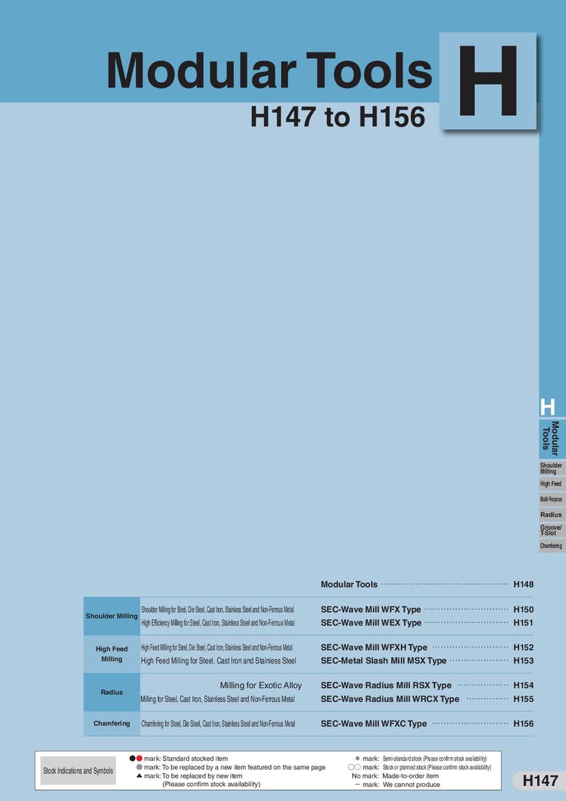 Каталог Sumitomo модульные фрезерные системы
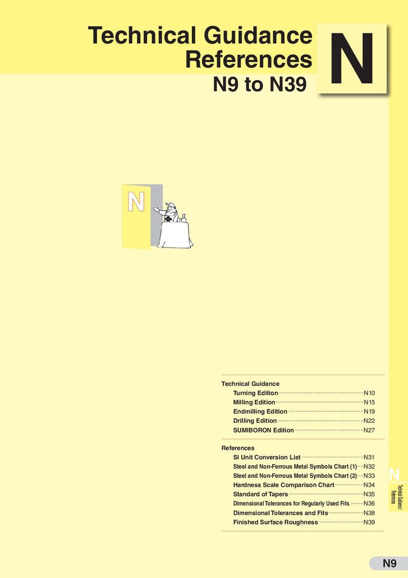 Техническая информация Sumitomo
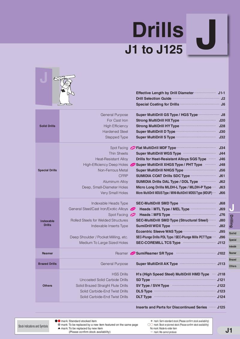 Каталог Sumitomo сверла и развертки
 Каталог Sumitomo резьбонарезной инструмент
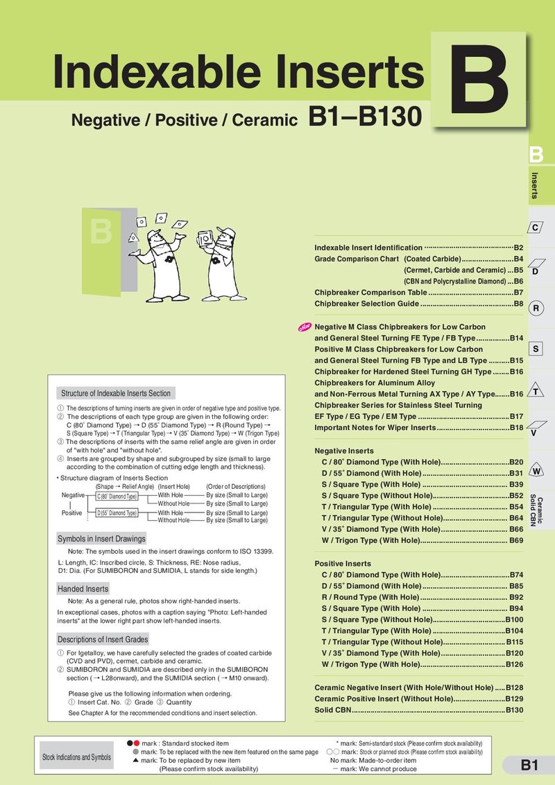 Каталог Sumitomo твердосплавные пластины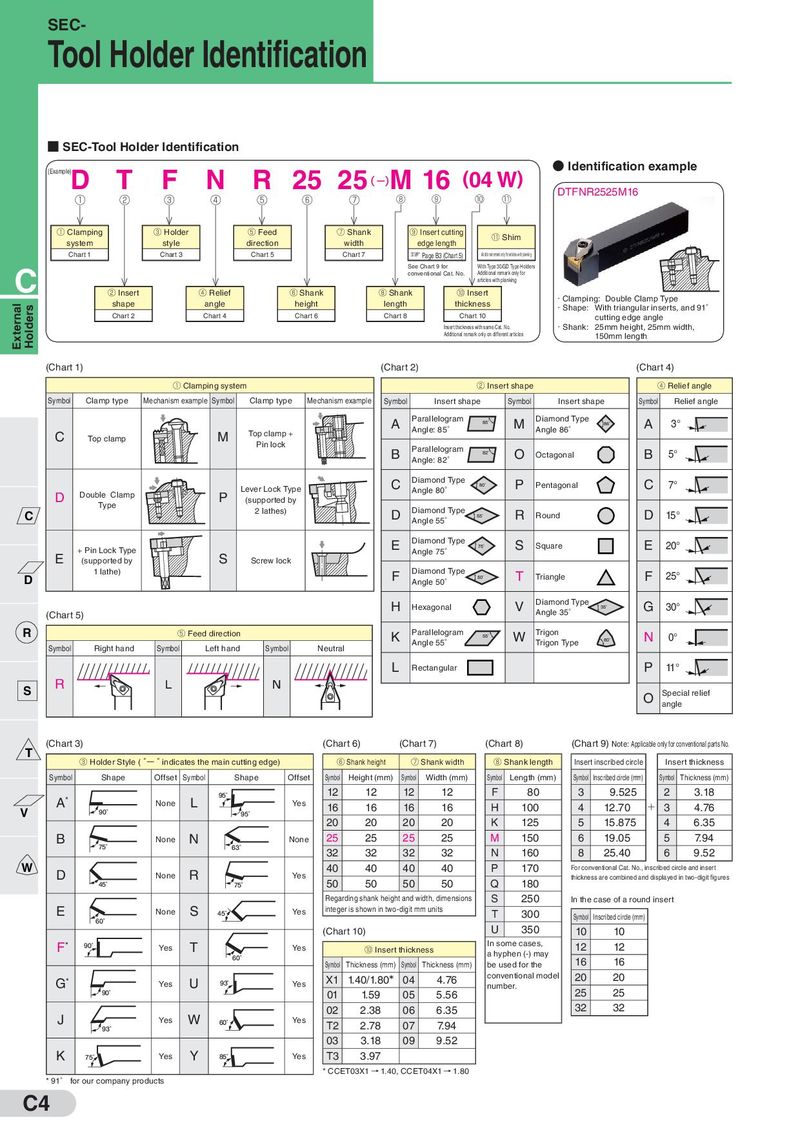
SEC- Tool Holder Identification ■ SEC-Tool Holder Identification (Example) ● Identification example D T F N R 25 25 (−) M 16 (04 W) DTFNR2525M16 ① ② ③ ④ ⑤ ⑥ ⑦ ⑧ ⑨ ⑩ ⑪ ① Clamping ③ Holder ⑤ Feed ⑦ Shank ⑨ Insert cutting ⑪ Shim system style direction width edge length Chart 1 Chart 3 Chart 5 Chart 7 ☞ Page B3 (Chart 5) Additional remark only for articles with planking See Chart 9 for With Type 30/GD Type Holders C conventional Cat. No. Additional remark only for articles with planking ② Insert ④ Relief ⑥ Shank ⑧ Shank ⑩ Insert ・Clamping: Double Clamp Type shape angle height length thickness ・Shape: With triangular inserts, and 91 External Holders Chart 2 Chart 4 Chart 6 Chart 8 Chart 10 cutting edge angle Insert thickness with same Cat. No. ・Shank: 25mm height, 25mm width, Additional remark only on different articles 150mm length (Chart 1) (Chart 2) (Chart 4) ① Clamping system ② Insert shape ④ Relief angle Symbol Clamp type Mechanism example Symbol Clamp type Mechanism example Symbol Insert shape Symbol Insert shape Symbol Relief angle Parallelogram Diamond Type A Angle: 85° 85˚ M Angle 86° 86˚ A 3° Top clamp + C Top clamp M Pin lock Parallelogram B Angle: 82° 82˚ O Octagonal B 5° Diamond Type Lever Lock Type C Angle 80° 80˚ P Pentagonal C 7° Double Clamp D Type P (supported by 2 lathes) Diamond Type C D Angle 55° 55˚ R Round D 15° Diamond Type + Pin Lock Type E Angle 75° 75˚ S Square E 20° E (supported by S Screw lock 1 lathe) Diamond Type D F Angle 50° 50˚ T Triangle F 25° Diamond Type H Hexagonal V Angle 35° 35˚ G 30° (Chart 5) R ⑤ Feed direction Parallelogram Trigon K Angle 55° 55˚ W Trigon Type 80˚ N 0° Symbol Right hand Symbol Left hand Symbol Neutral L Rectangular P 11° R L N S Special relief O angle (Chart 3) (Chart 6) (Chart 7) (Chart 8) (Chart 9) Note: Applicable only for conventional parts No. T ③ Holder Style ( ー indicates the main cutting edge) ⑥ Shank height ⑦ Shank width ⑧ Shank length Insert inscribed circle Insert thickness Symbol Shape Offset Symbol Shape Offset Symbol Height (mm) Symbol Width (mm) Symbol Length (mm) Symbol Inscribed circle (mm) Symbol Thickness (mm) 95˚ 12 12 12 12 F 80 3 9.525 2 3.18 A* None L Yes 16 16 16 16 H 100 4 12.70 + 3 4.76 V 90˚ 95˚ 20 20 20 20 K 125 5 15.875 4 6.35 B 75˚ None N None 25 25 25 25 M 150 6 19.05 5 7.94 63˚ 32 32 32 32 N 160 8 25.40 6 9.52 W 40 40 40 40 P 170 For conventional Cat. No., inscribed circle and insert D None R Yes thickness are combined and displayed in two-digit figures 45˚ 75˚ 50 50 50 50 Q 180 Regarding shank height and width, dimensions S 250 In the case of a round insert E None S 45˚ Yes integer is shown in two-digit mm units T 300 Symbol Inscribed circle (mm) 60˚ (Chart 10) U 350 10 10 * In some cases, F 90˚ Yes T Yes ⑩ Insert thickness a hyphen (-) may 12 12 60˚ Symbol Thickness (mm) Symbol Thickness (mm) be used for the 16 16 conventional model 20 20 G* Yes U 93˚ Yes X1 1.40/1.80* 04 4.76 number. 90˚ 01 1.59 05 5.56 25 25 02 2.38 06 6.35 32 32 J Yes W 60˚ Yes T2 2.78 07 7.94 93˚ 03 3.18 09 9.52 K 75˚ Yes Y 85˚ Yes T3 3.97 * CCET03X1 → 1.40, CCET04X1 → 1.80 * 91° for our company products C4