Общий каталог Osawa 2021 - страница 429
Навигация
 Общий каталог Osawa 2018
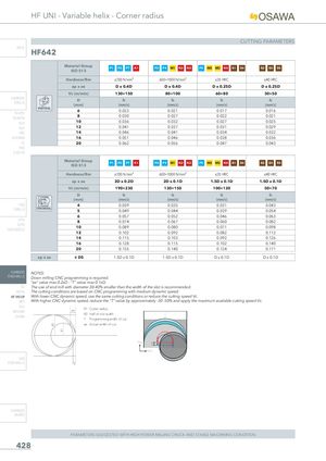
HF UNI - Variable helix - Corner radius CUTTING PARAMETERS INFO HF642 Material GroupISO 513 P1 P2 P7 K1 P3 P4 M1 K2 K3 P5 M2 M3 K4 S1 S4 S2 S3 S5 Hardness/Rm ≤700 N/mm² 600÷1000 N/mm² ≤35 HRC ≤40 HRC ap x ae D x 0.4D D x 0.4D D x 0.25D D x 0.25D Vc (m/min) 130÷150 80÷100 60÷80 30÷50 CARBIDEDRILLS D fz fz fz fz(mm)(mm/z)(mm/z)(mm/z)(mm/z) VERTICAL 6 0.023 0.021 0.017 0.016 PU-HPU TA-4HTA 8 0.030 0.027 0.022 0.021 SUH 10 0.036 0.032 0.027 0.025 ALH 12 0.041 0.037 0.031 0.029 HRC 14 0.046 0.041 0.034 0.032 SUH MINI 16 0.051 0.046 0.038 0.036 HL 20 0.062 0.056 0.047 0.043 HSD C-SD-TA Material Group P1 P2 P7 K1 P3 P4 M1 K2 K3 P5 M2 M3 K4 S1 S4 S2 S3 S5 ISO 513 Hardness/Rm ≤700 N/mm² 600÷1000 N/mm² ≤35 HRC ≤40 HRC ap x ae 2D x 0.2D 2D x 0.1D 1.5D x 0.1D 1.5D x 0.1D Vc (m/min) 190÷230 130÷150 100÷120 50÷70 D fz fz fz fz (mm) (mm/z) (mm/z) (mm/z) (mm/z) HSS 4 0.039 0.035 0.031 0.043 DRILLS TROCHOIDAL 5 0.049 0.044 0.039 0.054 6 0.057 0.052 0.046 0.063 LFTA 8 0.074 0.067 0.060 0.082 SUTAHSS-HSS/CO 10 0.089 0.080 0.071 0.098 12 0.102 0.092 0.082 0.112 14 0.115 0.103 0.092 0.126 16 0.128 0.115 0.102 0.140 20 0.155 0.140 0.124 0.171 ap x ae ≤ D5 1.5D x 0.1D 1.5D x 0.1D D x 0.1D D x 0.1D CARBIDE NOTES: END-MILLS Down milling CNC programming is required. “ae” value max 0.2xD - “T” value max 0.1xD. G2 The use of end mill with diameter 30-40% smaller than the width of the slot is recommended. MDTA The cutting conditions are based on CNC programming with medium dynamic speed. HF VH/UP With lower CNC dynamic speed, use the same cutting conditions or reduce the cutting speed Vc. MEF With higher CNC dynamic speed, reduce the “T” value by approximately -30 -50% and apply the maximum available cutting speed Vc. ALUMEX/MH ae R1 Cutter radius UH/MH R2 Half of slot width T Programming width of cut ae Actual width of cut Y (+) Y X (+) HSS END-MILLS T CARBIDE BURRS PARAMETERS SUGGESTED WITH HIGH POWER MILLING CHUCK AND STABLE MACHINING CONDITION 428 R2 R1