Общий каталог Mitsubishi 2020 - 2021 - страница 71
Навигация
 Каталог Mitsubishi Materials запасные части
 Каталог Mitsubishi Materials резьбонарезной инструмент
 Каталог Mitsubishi Materials СНП с CBN и PCD для токарной обработки
 Каталог Mitsubishi Materials сверлильные инструменты
 Каталог Mitsubishi Materials расточной инструмент
 Каталог Mitsubishi Materials пластины для точения
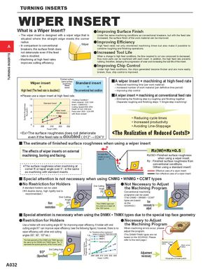
TURNING INSERTS
Surface Roughness
Rz(!inch)
Theoretical Surface
Roughness Rz (!inch)
TURNING INSERTS
WIPER INSERT
What is a Wiper Insert? a Improving Surface Finish
• The wiper insert is designed with a wiper edge that is Under the same machining conditions as conventional breakers, but with the feed rate
situated where the straight edge meets the corner increased, the surface finish of the work material can be improved.
radius.A• In comparison to conventionalbreakers, the surface finish does Wiper a Improving EfficiencyHigh feed rates not only shortened machining times but also make it possible tocombine roughing and finishing operations.
not deteriorate even if the feed a Increased Tool Life
rate is doubled. When a change to high feed conditions, the time required to cut one component is decreased,
• Machining at high feed rates thus more parts can be machined with each insert. In addition, the high feed rate prevents
improves cutting efficiency. rubbing, therefore, delaying the progression of wear and increasing the tool life of the insert.
a Improving Chip Control
Under high feed conditions, the chips generated become thicker and are more easily
broken, thus, chip control is improved.
Finished surfaceWiper insertSame surfaceroughnessStandard insert++ yA wiper insert + machining at high feed rate• Reduced machining time (per work material)• Increased number of work material (per definitive time period)
High feed (The feed rate is doubled.) The conventional feed condition • Improving chip control
*Please use a wiper insert at high feed rate.