Общий каталог Mitsubishi 2020 - 2021 - страница 1218
Навигация
 Каталог Mitsubishi Materials запасные части
 Каталог Mitsubishi Materials резьбонарезной инструмент
 Каталог Mitsubishi Materials СНП с CBN и PCD для токарной обработки
 Каталог Mitsubishi Materials сверлильные инструменты
 Каталог Mitsubishi Materials расточной инструмент
 Каталог Mitsubishi Materials пластины для точения
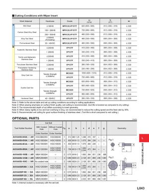
y Cutting Conditions with Wiper Insert (inch) Work Material Hardness Grade vc(SFM) fz(IPT) ap P Mild Steel <180HB MP6120,VP15TF 820 (655 ─ 985) .012 (.008 ─ .016) < .020 180 ─ 280HB MP6120,VP15TF 720 (560 ─ 885) .012 (.008 ─ .016) < .020 Carbon Steel,Alloy Steel 280 ─ 350HB MP6120,VP15TF 460 (330 ─ 590) .012 (.008 ─ .016) < .020 Alloy Tool Steel < 350HB(Annealing)MP6120,VP15TF 460 (330 ─ 590) .006 (.004 ─ .008) < .020 Pre-hardened Steel 35 ─ 45HRC MP6120,VP15TF 460 (330 ─ 590) .006 (.004 ─ .008) < .020 M < 200HB VP15TF 410 (330 ─ 490) .006 (.004 ─ .008) < .020 Austenitic Stainless Steel > 200HB VP15TF 330 (245 ─ 410) .006 (.004 ─ .008) < .020 Ferritic and Maltensitic < 200HB VP15TF 410 (330 ─ 490) .006 (.004 ─ .008) < .020 Stainless Steel > 200HB VP15TF 330 (245 ─ 410) .006 (.004 ─ .008) < .020 Two-phase Stainless Steel < 280HB VP15TF 260 (195 ─ 330) .004 (.002 ─ .006) < .020 Precipitation HardeningStainless Steel< 450HB VP15TF 230 (165 ─ 295) .004 (.002 ─ .006) < .020 K Gray Cast Iron Tensile Strength MC5020 1050 (820 ─ 1310) .012 (.008 ─ .016) < .020< 350MPaVP15TF720 (490 ─ 985).012 (.008 ─ .016)< .020 Tensile Strength MC5020 820 (655 ─ 985) .008 (.004 ─ .012) < .020 < 450MPa VP15TF 655 (490 ─ 820) .008 (.004 ─ .012) < .020 Ductile Cast Ilon Tensile Strength MC5020 720 (655 ─ 820) .008 (.004 ─ .012) < .020 < 800MPa VP15TF 560 (490 ─ 655) .008 (.004 ─ .012) < .020 H Hardened Steel 40 ─ 55HRC VP15TF 260 (195 ─ 330) .006 (.004 ─ .008) < .020 Note 1) Refer to the above table and set up cutting conditions according to cutting applications. Note 2) When placing emphasis on surface finish quality, wet cutting is recommended. (tool life is lowered as compared to dry cutting) Note 3) The recommended depth of cut differs according to insert geometry. Note 4) When clamp rigidity is low and tool overhang is long, we recommended to reduce the cutting speed and the feed rate by 30%. Note 5) Recommended wet cutting for good surface finishing of stainless steel. (Tool life is short compared to wet cutting.) OPTIONAL PARTS ( inch) Set Bolt Tool Holder Number With CoolantHoleWithout Coolant Hole Fig.a b c d e f g Geometry Order Number Order Number AHX440S-040AooAR HSC08025H HSC08040 1 .512 M8×1.25 1.299 .315 .197 ‒ ‒AHX440S-050AooARHSC10030HHSC100351.630M10×1.51.575.394.236‒‒Fig.1L AHX440S-063AooAR HSC10030H HSC10035 1 .630 M10×1.5 1.575 .394 .236 ‒ ‒ AHX440S-080AooAR HSC12035H HSC12035HSC120451 .709 M12×1.75 1.8502.244.472.394 ‒ ‒ e d c AHX440S-100BooAR MBA16033H ‒ 2 1.575 M16×2 1.693 .394 .551 .236 .906 AHX440S-125BooAR MBA20040H ‒ 2 1.969 M20×2.5 2.126 .551 .669 .236 1.063 Fig.2 f AHX440S-160CooNR No coolant hole ‒ 2 1.969 M20×2.5 2.126 .551 .669 .236 1.063 AHX440SR080ooCA HSC12035H HSC12035HSC120451 .709 M12×1.75 1.8502.244.472.394 ‒ ‒ AHX440SR100ooDA MBA16033H ‒ 2 1.575 M16×2 1.693 .394 .551 .236 .906AHX440SR125ooEAMBA20040H‒21.969M20×2.52.126.551.669.2361.063edc AHX440SR160ooFA MBA24045H ‒ 2 2.559 M24×3 2.323 .551 .669 .394 1.457 Note 1) Internal coolant is necessary with the set bolt. L043 aa bb g INDEXABLE MILLING