Общий каталог Mitsubishi 2020 - 2021 - страница 1039
Навигация
 Каталог Mitsubishi Materials запасные части
 Каталог Mitsubishi Materials резьбонарезной инструмент
 Каталог Mitsubishi Materials СНП с CBN и PCD для токарной обработки
 Каталог Mitsubishi Materials сверлильные инструменты
 Каталог Mitsubishi Materials расточной инструмент
 Каталог Mitsubishi Materials пластины для точения
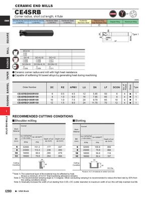
SQUAREBALLRADIUSTAPERBARRELROUGHINGSOLID END MILLS DC DN No. of Flutes DCONStock CERAMIC END MILLS CE4SRB 30° Corner radius, short cut length, 4 flute CERAMIC Carbon Steel, Alloy Steel, Cast Iron Tool Steel, Pre-Hardened Steel, Hardened Steel Hardened Steel(<30HRC)( < 45HRC)( < 55HRC)Hardened Steel(>55HRC)AusteniticTitanium Alloy,Stainless SteelHeat Resistant AlloyCopper AlloyAluminum Alloy e Type 1 RE APMX LU LF DC<12 0.02 - 0.02 DC=6 DC=8,10 DC=12 - 0.008 - 0.009 - 0.011 - 0.028 - 0.029 - 0.031 DCON=6 DCON=8,10 DCON=12 0 0 0 - 0.008 - 0.009 - 0.011 aCeramic corner radius end mill with high heat resistance. aCapable of softening Ni based alloys by generating heat during machining (mm) Order Number DC RE APMX LU DN LF DCON Type CE4SRBD0600R050 6 0.5 4.5 12 5.85 50 6 4 a 1 CE4SRBD0800R100 8 1.0 6.0 16 7.85 60 8 4 a 1 CE4SRBD1000R100 10 1.0 7.5 20 9.70 65 10 4 a 1 CE4SRBD1200R150 12 1.5 9.0 24 11.70 70 12 4 a 1 I RECOMMENDED CUTTING CONDITIONS y Shoulder milling y Slotting Inconel Inconel Work Work Material Material DC Vc=1970SFM(1150-3300)fz=.0016IPT Depth of cut Depth of cut DC Vc=1970SFM(1150-3300)fz=.0008IPTDepth of cut (mm) RPM IPM ap (inch) ae (inch) (mm) RPM IPM ap (inch) 6 32000 151.2 .177 .047 6 32000 100.8 .059 8 24000 113.4 .236 .063 8 24000 75.6 .098 10 19000 89.8 .295 .079 10 19000 59.8 .118 12 16000 75.6 .354 .094 12 16000 50.4 .157 ae DC CuttingCondition ap CuttingCondition ap DC:Dia. * Note 1) The outermost layer of the material may be affected by heat. *Leave .012" of material on bottom and side Ensure a minimum of 0.012” final machining allowance remains. Note 2) The recommended ramping angle is 1.5 degree. When conducting ramping it is recommended to reduce the feed rate by 50% from the cutting conditions shown. Note 3) Gradually increase the width of cut starting from 0.05 x DC (cutter diameter) to maximum width of cut, this will help maintain tool life. I280 a : USA Stock