Каталог Iscar токарные пластины ISO 2022 - страница 69
Навигация
 Каталог Iscar инструмент для обработки отверстий
 Каталог Iscar инструмент для токарной обработки
 Каталог Iscar концевые фрезы со сменными пластинами 2022
 Каталог Iscar инструментальные блоки
 Каталог Iscar торцевые фрезы 2022
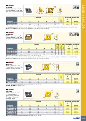
IC8250 IC807 IC907IC908IC907 IC907 ISOTURN INSERTS 80° 95º CCET-WF 95º 95º 80° Rhombic Inserts with a 7° 86° Positive Flank and a Wiper Near IC D1 the Corner for High Feed Finishing RE 7° 0.3 RE L S Dimensions Recommended Machining Data ap f Designation L IC S RE D1 (mm) (mm/rev) CCET 0602005-WF 6.30 6.35 2.38 0.05 2.80 • 0.05-2.00 0.01-0.20 CCET 09T3005-WF 9.50 9.52 3.97 0.05 4.40 • 0.05-2.00 0.01-0.20 • For user guide and cutting speed recommendations, see pages 122-134, 236-248 For tools, see pages: A/E/S-SCLCR/L (111) • C#-SCLCR/L-JHP (54) • E-SCLCR/L-HEAD (110) • NQCH-SCACR/L-JHP (55) • PCLCR/L-S (55) • PCLCR/L-S-JHP (56) • SCACR/L-S (55) • SCLCR-PAD (55) • SCLCR/L (54) • AVC-SCLCR/L (95) • PCLCR/L-JHP-MC (56) 80° 95º 99° CCMT-WG 95º95º 91° 80° Rhombic Inserts with a 7° Positive Flank and a Wiper Near IC D1 the Corner for High Feed Finishing 7° RE L S Dimensions Tough 1 Hard Recommended Machining Data ap f Designation L IC S RE D1 (mm) (mm/rev) CCMT 060204-WG 6.30 6.35 2.38 0.40 2.80 • • 0.40-2.00 0.10-0.35 CCMT 09T304-WG 9.70 9.52 3.97 0.40 4.40 • 0.40-2.00 0.14-0.30 CCMT 09T308-WG 9.70 9.52 3.97 0.80 4.40 • 0.50-2.50 0.20-0.38 CCMT 120408-WG 12.90 12.70 4.76 0.80 5.50 • 0.50-3.00 0.20-0.36 • For user guide and cutting speed recommendations, see pages 122-134, 236-248 For tools, see pages: A/E/S-SCLCR/L (111) • C#-SCLCR/L-JHP (54) • E-SCLCR/L-HEAD (110) • NQCH-SCACR/L-JHP (55) • PCLCR/L-S (55) • PCLCR/L-S-JHP (56) • SCACR/L-S (55) • SCLCR-PAD (55) • SCLCR/L (54) • AVC-SCLCR/L (95) • PCLCR/L-JHP-MC (56) EPGT-F1P 75˚ 11˚ 100º 75° Rhombic Inserts with a Positive Flank for Very Low Finish IC D1 Turning Conditions on Steel RE L S Dimensions Recommended Machining Data ap f Designation L IC S RE D1 (mm) (mm/rev) EPGT 03X101-F1P 3.70 3.57 1.39 0.10 1.90 • 0.10-0.50 0.01-0.05 EPGT 03X102-F1P 3.70 3.57 1.39 0.20 1.90 • 0.10-0.50 0.02-0.10 EPGT 03X104-F1P 3.70 3.57 1.39 0.40 1.90 • 0.10-0.50 0.05-0.15 • For user guide and cutting speed recommendations, see pages 122-134, 236-248 For tools, see pages: A/E-SEXPR/L-03 (112) CPGT-SM 80° 95º 80° Rhombic Inserts with an 11° Positive Flank for IC D1 Semi-Finishing and Finish Turning on Soft Materialsand Exotic Alloys 11°REL S Dimensions Recommended Machining Data ap f Designation L IC S RE D1 (mm) (mm/rev) CPGT 060201-SM 6.45 6.35 2.38 0.10 2.80 • 0.25-2.00 0.05-0.20 CPGT 060202-SM 6.45 6.35 2.38 0.20 2.80 • 0.25-2.00 0.05-0.30 CPGT 060204-SM 6.45 6.35 2.38 0.40 2.80 • 0.50-3.00 0.10-0.35 CPGT 09T301-SM 9.67 9.52 3.97 0.10 4.40 • 0.25-2.00 0.05-0.25 CPGT 09T302-SM 9.67 9.52 3.97 0.20 4.40 • 0.50-2.50 0.10-0.30 CPGT 09T304-SM 9.67 9.52 3.97 0.40 4.40 • 0.60-3.50 0.10-0.35 • For user guide and cutting speed recommendations, see pages 122-134, 236-248 189