Каталог Iscar обработка канавок 2022 - страница 34
Навигация

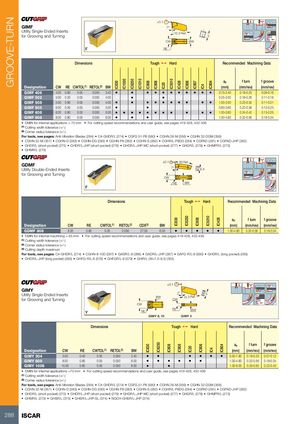
GROOVE-TURN IC830 IC1030 IC8250 IC1010 IC808IC830 IC908IC8250 IC20 IC5010IC808 IC830 IC428IC908 IC806IC8250 IC20 IC907IC808 IC4IC806 IC804IC5010IC4 IC428 IC804 ±0.1 GIMF 7º Utility Single-Ended Inserts 15.3 Ref. for Grooving and Turning 5 CW BW RE Dimensions Tough 1 Hard Recommended Machining Data ap f turn f groove Designation CW RE CWTOL(1) RETOL(2) BW (mm) (mm/rev) (mm/rev) GIMF 406 4.00 0.60 0.05 0.050 3.40 • • • • • • • • • • • 0.75-2.40 0.19-0.25 0.09-0.16 GIMF 502 5.00 0.20 0.05 0.050 4.00 • • 0.25-3.00 0.18-0.26 0.11-0.18 GIMF 508 5.00 0.80 0.05 0.050 4.00 • • • • • • • • • • 1.00-3.00 0.23-0.35 0.11-0.21 GIMF 605 6.00 0.50 0.05 0.050 5.00 • • 0.60-3.60 0.22-0.36 0.13-0.23 GIMF 608 6.00 0.80 0.05 0.050 5.00 • • • • • • • • • • • 1.00-3.60 0.24-0.42 0.13-0.25 GIMF 808 8.00 0.80 0.05 0.050 6.00 • • • 1.00-4.80 0.32-0.56 0.18-0.34 • DMIN for internal applications = 70 mm • For cutting speed recommendations and user guide, see pages 419-428, 432-436 (1) Cutting width tolerance (+/-) (2) Corner radius tolerance (+/-) For tools, see pages: Anti-Vibration Blades (284) • C#-GHDR/L (274) • CGFG 51-P8 (580) • CGHN 26-M (356) • CGHN 32-DGM (358) • CGHN 32-M (357) • CGHN-D (283) • CGHN-DG (283) • CGHN-P8 (283) • CGHN-S (282) • CGHR/L-P8DG (284) • CGPAD (281) • CGPAD-JHP (282) • GHDR/L (short pocket) (275) • GHDR/L-JHP (short pocket) (276) • GHDR/L-JHP-MC (short pocket) (277) • GHGR/L (278) • GHMPR/L (273) • GHMR/L (273) ±0.1 30 Ref. GDMF Utility Double-Ended Inserts 7° 6.4 for Grooving and Turning CW RE BW Dimensions Tough 1 Hard Recommended Machining Data ap f turn f groove Designation CW RE CWTOL(1) RETOL(2) CDX(3) BW (mm) (mm/rev) (mm/rev) GDMF 808 8.00 0.80 0.05 0.050 27.00 6.00 • • • • • 1.00-4.80 0.32-0.56 0.18-0.34 • DMIN for internal machining = 65 mm • For cutting speed recommendations and user guide, see pages 419-428, 432-436 (1) Cutting width tolerance (+/-) (2) Corner radius tolerance (+/-) (3) Cutting depth maximum For tools, see pages: C#-GHDR/L (274) • CGHN-8-10D (287) • GADR/L-8 (286) • GADR/L-JHP (287) • GAFG-R/L-8 (580) • GHDR/L (long pocket) (285) • GHDR/L-JHP (long pocket) (285) • GHFG-R/L-8 (579) • GHFGR/L-8 (579) • GHIR/L (W=7.0-8.3) (355) ±0.1 GIMY Utility Single-Ended Insertsfor Grooving and Turning 7˚ 5BW15.3 Ref.CW CW RE RE BW GIMY 8, 10 GIMY 3 Dimensions Tough 1 Hard Recommended Machining Data ap f turn f groove Designation CW RE CWTOL(1) RETOL(2) BW (mm) (mm/rev) (mm/rev) GIMY 304 3.00 0.40 0.05 0.050 2.40 • • • • • • 0.50-1.80 0.16-0.20 0.07-0.12 GIMY 808 8.00 0.80 0.05 0.050 6.00 • • • • • • 1.00-4.80 0.32-0.56 0.18-0.34 GIMY 1008 10.00 0.80 0.05 0.050 8.00 • • 1.00-6.00 0.35-0.65 0.22-0.40 • DMIN for internal applications =70 mm • For cutting speed recommendations and user guide, see pages 419-428, 432-436 (1) Cutting width tolerance (+/-) (2) Corner radius tolerance (+/-) For tools, see pages: Anti-Vibration Blades (284) • C#-GHDR/L (274) • CGFG 51-P8 (580) • CGHN 26-M (356) • CGHN 32-DGM (358) • CGHN 32-M (357) • CGHN-D (283) • CGHN-DG (283) • CGHN-P8 (283) • CGHN-S (282) • CGHR/L-P8DG (284) • CGPAD (281) • CGPAD-JHP (282) • GHDR/L (short pocket) (275) • GHDR/L-JHP (short pocket) (276) • GHDR/L-JHP-MC (short pocket) (277) • GHGR/L (278) • GHMPR/L (273) • GHMR/L (273) • GHSR/L (373) • GHSR/L-JHP-SL (374) • NQCH-GHSR/L-JHP (374) 288 ISCAR
 Каталог Iscar монолитные концевые фрезы и система multi-master
 Каталог Iscar сверла ружейные и для глубокого сверления 2022
 Каталог Iscar токарные державки ISO 2022
 Каталог Iscar инструмент для обработки алюминиевых колёс
 Каталог Iscar инструментальная оснастка 2022