Каталог Iscar инструмент для мелкоразмерной обработки - страница 38
Навигация
 Каталог Iscar дисковые фрезы и фрезерные пластины 2022
 Каталог Iscar инструмент для внутренней обработки
 Каталог Iscar инструмент для обработки алюминиевых колёс
 Каталог Iscar державки и пластины для нарезания резьбы 2022
 Каталог Iscar токарный инструмент для нарезания канавок
 Каталог Iscar новые продукты 2018
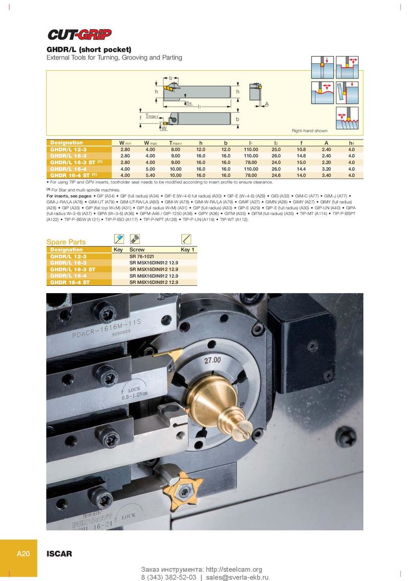
GHDR/L (short pocket)
External Tools for Turning, Grooving and Parting
l2
h h
h 4 A
l1
f Tmax-r
b
W Right-hand shown
Designation W min W max T max-r h b l 1 l 2 f A h 4
GHDR/L 12-3 2.80 4.00 8.00 12.0 12.0 110.00 25.0 10.8 2.40 4.0
GHDR/L 16-3 2.80 4.00 9.00 16.0 16.0 110.00 26.0 14.8 2.40 4.0
GHDR/L 16-3 ST (1) 2.80 4.00 9.00 16.0 16.0 78.00 24.0 15.0 2.20 4.0
GHDR/L 16-4 4.00 5.00 10.00 16.0 16.0 110.00 26.0 14.4 3.20 4.0
GHDR 16-4 ST (1) 4.00 5.40 10.00 16.0 16.0 78.00 24.6 14.0 3.40 4.0
• For using TIP and GPV inserts, toolholder seat needs to be modified according to insert profile to ensure clearance.
(1) For Star and multi-spindle machines.
For inserts, see pages: • GIF (A34) • GIF (full radius) (A34) • GIF-E (W=4-6 full radius) (A30) • GIF-E (W=4-6) (A29) • GIG (A32) • GIM-C (A77) • GIM-J (A77) •
GIM-J-RA/LA (A78) • GIM-UT (A79) • GIM-UT-RA/LA (A80) • GIM-W (A78) • GIM-W-RA/LA (A79) • GIMF (A27) • GIMN (A28) • GIMY (A27) • GIMY (full radius)
(A28) • GIP (A33) • GIP (flat top W