Общий каталог Ingersoll 2011 - страница 463
Навигация
- 0003 Table of Contents
- 0006 End Mills
- 0064 Long Edge
- 0104 0Deg Face Mills
- 0160 Face Mills
- 0202 Slotters
- 0218 Form Mills
- 0236 Profile Mills
- 0302 Milling Tech
- 0384 Solid Carbide
- 0448 Solid Carbide Tech
- 0474 Holemaking & Thread Milling
- 0666 Holemaking & Thread Milling Tech
- 0720 Innofit Top On Toolholders
- 0738 HSK Toolholders
- 0774 CAT Toolholders
- 0796 BT Toolholders
- 0816 Adaptions Accessories
- 0872 Turning Inserts
- 1024 Turning Holders
- 1144 Turning Tech
- 1174 Threading Inserts
- 1242 Threading Holders
- 1256 Threading Tech
- 1268 T-Clamp
- 1344 T-Clamp Tech
- 1376 T-CAP
- 1388 T-CAP Tech
- 1394 Product_Index

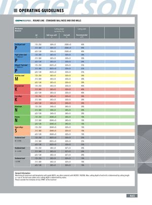
OPERATING GUIDELINES , ROUND LINE - STANDARD BALL NOSE AND END MILLS Workpiece Cutting depth Cutting width Material ap recomm. for DC Ball nose mill End mill Recommended in in in ae % Unalloyed steel .125-.250 .004 x D .0500 x D 40% P .312-.500 .004 x D .0500 x D 40% .625-1.00 .004 x D .0500 x D 40% High Carbon steel .125-.250 .003 x D .030 x D 30% < 1100N/mm² P .312-.500 .003 x D .030 x D 30%.625-1.00.003 x D.030 x D30% Alloyed / Tool steel .125-.250 .0025 x D .030 x D 25% < 1400N/mm² P .312-.500 .0025 x D .030 x D 25%.625-1.00.0025 x D.030 x D25% Stainless steel .125-.250 .003 x D .030 x D 30% M .312-.500 .003 x D .030 x D 30% .625-1.00 .003 x D .030 x D 30% Gray cast iron .125-.250 .003 x D .030 x D 40% K .312-.500 .003 x D .030 x D 40% .625-1.00 .003 x D .030 x D 40% Cast alloys .125-.250 .003 x D .030 x D 30% K .312-.500 .003 x D .030 x D 30% .625-1.00 .003 x D .030 x D 30% Aluminum .125-.250 .040 x D .040 x D 30% N .312-.500 .040 x D .040 x D 30% .625-1.00 .040 x D .040 x D 30% Plastics .125-.250 .0040 x D .040 x D 10% N .312-.500 .0040 x D .040 x D 10% .625-1.00 .0040 x D .040 x D 10% Super alloys .125-.250 .0040 x D .020 x D 10% S .312-.500 .0040 x D .020 x D 10% .625-1.00 .0040 x D .020 x D 10% Hardened steel .125-.250 .0025 x D .030 x D 25% 48 - 54 HRC .312-.500 .0025 x D .030 x D 25% .625-1.00 .0025 x D .030 x D 25% Hardened steel .125-.250 .002 x D .027 x D 20% 54 - 63 HRC .312-.500 .002 x D .027 x D 20% .625-1.00 .002 x D .027 x D 20% Hardened steel .125-.250 .002 x D .024 x D 10% > 63 HRC .312-.500 .002 x D .024 x D 10% .625-1.00 .002 x D .024 x D 10% General Information: Machining of aluminum and duroplastics with grade IN05S, any other materials with IN2005 / IN2006. Max. cutting depth of end mills is determined by cutting length a = xxx in; for ball nose cutters max. cutting depth is determined by radius. Please consider the limitation of max. RPM1 of the machine! 465
 Общий каталог Ingersoll 2016 - 2017
 Общий каталог Ingersoll 2014
 Каталог Ingersoll инструмент для нарезания резьбы
 Общий каталог Ingersoll 2013 - 2014
 Каталог Ingersoll новинки 2021