Общий каталог Ingersoll 2011 - страница 1347
Навигация
 Общий каталог Ingersoll 2016 - 2017
 Общий каталог Ingersoll 2014
 Каталог Ingersoll инструмент для нарезания резьбы
 Общий каталог Ingersoll 2013 - 2014
 Каталог Ingersoll новинки 2021
- 0003 Table of Contents
- 0006 End Mills
- 0064 Long Edge
- 0104 0Deg Face Mills
- 0160 Face Mills
- 0202 Slotters
- 0218 Form Mills
- 0236 Profile Mills
- 0302 Milling Tech
- 0384 Solid Carbide
- 0448 Solid Carbide Tech
- 0474 Holemaking & Thread Milling
- 0666 Holemaking & Thread Milling Tech
- 0720 Innofit Top On Toolholders
- 0738 HSK Toolholders
- 0774 CAT Toolholders
- 0796 BT Toolholders
- 0816 Adaptions Accessories
- 0872 Turning Inserts
- 1024 Turning Holders
- 1144 Turning Tech
- 1174 Threading Inserts
- 1242 Threading Holders
- 1256 Threading Tech
- 1268 T-Clamp
- 1344 T-Clamp Tech
- 1376 T-CAP
- 1388 T-CAP Tech
- 1394 Product_Index
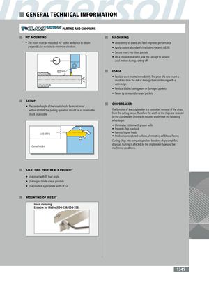
GENERAL TECHNICAL INFORMATION PARTING AND GROOVING 90° MOUNTING MACHINING • The insert must be mounted 90° to the workpiece to obtain • Consistency of speed and feed improves performance perpendicular surfaces to minimize vibration. • Apply coolant abundantly (excluding Ceramic AB30) • Secure insert into clean pockets • On a conventional lathe, lock the carriage to prevent axial motion during parting-off 90°±10´ USAGE • Replace worn inserts immediately. The price of a new insert is much less than the risk of damage from continuing with a worn edge. • Replace blades having worn or damaged pockets • Never try to repair damaged pockets SET-UP • The center height of the insert should be maintained CHIPBREAKER within ±0.004"The parting operation should be as close to the The function of the chipbreaker is a controlled removal of the chips chuck as possible from the cutting range. Therefore the width of the chips are reduced by the chipbreaker. Chips with reduced width have the following advantages • Eliminates friction with groove walls • Prevents chip overload ±(0.004") • Permits higher feeds • Produces unscratched surfaces, eliminating additional facing Curling chips into compact spirals or breaking chips simplifies Center height disposal. Curling is affected by the chipbreaker type and themachining conditions. SELECTING PREFERENCE PRIORITY • Use insert with 0° lead angle. • Use largest blade size as possible • Use smallest appropriate width of cut MOUNTING OF INSERT Insert clamping Extractor for Blades (EDG-23B, EDG-33B) 1349