Общий каталог Dijet 2018 - страница 97
Навигация
 Общий каталог Dijet 2012 на русском
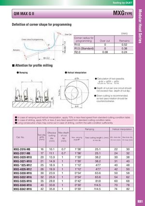
Tooling by DIJET QM MAX G II MXGTYPE Definition of corner shape for programming (mm) Corner radius for programming Over cut Remains R1.0 0 0.52 R1.5 (Standard) 0 0.38 R2.0 0.08 0.24 ■ Attention for profile milling ● Ramping ● Helical interpolation ● Calculation of tool passdia. φdc = φDh − φDc Tool pass dia. Bore dia. Tool dia. ● Depth of cut per one circuit should not exceed max. depth of cut ap. ● Down cutting is recommended, so tool pass rotation should be counterclockwise. ● In case of ramping and helical interpolation, apply 70% or less feed speed from standard cutting condition table. ● In case of drilling, apply 50% or less Z axis feed speed from standard cutting condition table. ● Long consecutive chips may come out in case of drilling, confirm the safe condition sufficiently. Ramping Helical interpolation Effective Max.depth Cat. No. Tool dia.φDc(mm)cuttingdia.(mm)of cutap Max. ramping Total cutting length L (mm) Min. bore dia. Max.bore dia.(mm)angleθ°at max.apDh min (mm)Dh max (mm) MXG-2016-M8 16 10.1 0.7 1°36' 25.1 22 30 MXG-2017-M8 17 11.1 0.7 1°36' 25.1 24 32 MXG-3020-M10 20 13.9 1 1°30' 38.2 30 38 MXG-3021-M10 21 14.9 1 1°30' 38.2 31 40 MXG-*025-M12 25 18.9 1 1°12' 47.7 40 48 MXG-4026-M12 26 19.9 1 1°12' 47.7 42 50 MXG-5030-M16 30 23.9 1 0°54' 63.6 50 58 MXG-5032-M16 32 25.9 1 0°54' 63.6 54 62 MXG-5035-M16 35 28.8 1 0°42' 81.8 60 68 MXG-6040-M16 40 33.8 1 0°30' 114.5 70 78 MXG-6042-M16 42 35.8 1 0°30' 114.5 74 82 B081