Общий каталог Dijet 2018 - страница 42
Навигация

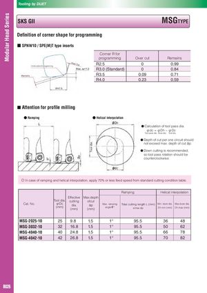
Modular Head Series Tooling by DIJET SKS GII MSGTYPE Definition of corner shape for programming ■ SPNW10 / SPE(M)T type inserts Corner R for programming Over cut Remains R2.5 0 0.99 R3.0 (Standard) 0 0.84 R3.5 0.09 0.71 R4.0 0.23 0.59 ■ Attention for profile milling ● Ramping ● Helical interpolation ● Calculation of tool pass dia. φdc = φDh − φDc Tool pass dia. Bore dia. Tool dia. ● Depth of cut per one circuit should not exceed max. depth of cut ap. ● Down cutting is recommended, so tool pass rotation should be counterclockwise. ◎ In case of ramping and helical interpolation, apply 70% or less feed speed from standard cutting condition table. Ramping Helical interpolation Effective Max.depth Cat. No. Tool dia.φDc(mm)cuttingdia.(mm)ofcutap(mm) Max. ramping Total cutting length L (mm) Min. bore dia. Max.bore dia.angleθ°atmax.apDh min (mm)Dh max (mm) MSG-2025-10 25 9.8 1.5 1° 95.5 36 48 MSG-3032-10 32 16.8 1.5 1° 95.5 50 62 MSG-4040-10 40 24.8 1.5 1° 95.5 66 78 MSG-4042-10 42 26.8 1.5 1° 95.5 70 82 B026
 Общий каталог Dijet 2012 на русском