Каталог Widia инструментальная оснастка - страница 34
Навигация
 Каталог Widia достижения 2021
 Брошюра Widia решения для аэрокосмической промышленности
 Брошюра Widia техническое руководство
 Каталог Widia токарный инструмент 2020
 Каталог Widia цельные концевые фрезы
 Каталог Widia техническое руководство по разверткам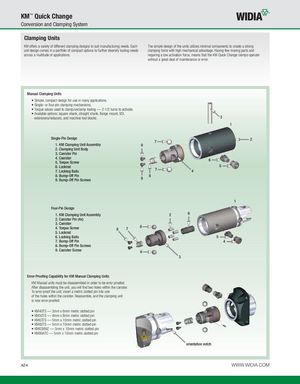
Clamping Units
KM offers a variety of different clamping designs to suit manufacturing needs. Each The simple design of the units utilizes minimal components to create a strong unit design comes in a portfolio of compact options to further diversify tooling needs clamping force with high mechanical advantage. Having few moving parts and across a multitude of applications. requiring a low activation force, means that the KM Quick Change clamps operate without a great deal of maintenance or error.
Manual Clamping Units
- Simple, compact design for use in many applications.
- Single- or four-pin clamping mechanisms.
- Torque values used to clamp/unclamp tooling — 2-1/2 turns to activate.
- Available options: square shank, straight shank, flange mount, VDI, extensions/reducers, and machine tool blocks. 3
1
Single-Pin Design 2 7 1. KM Clamping Unit Assembly 9 2. Clamping Unit Body 3. Canister Pin 4. Canister 6 5. Torque Screw 6. Lockrod 5
7. Locking Balls 7 4
8. Bump-Off Pin 8 9. Bump-Off Pin Screws 9
1 Four-Pin Design
1. KM Clamping Unit Assembly 2 9
2. Canister Pin (4x) 3. Canister 4. Torque Screw 6 8 7 5. Lockrod 6. Locking Balls 5 7. Bump-Off Pin 4 8. Bump-Off Pin Screws 9. Canister Screw 6 3
Error-Proofing Capability for KM Manual Clamping Units KM Manual units must be disassembled in order to be error proofed. After disassembling the unit, you will find two holes within the canister. To error-proof the unit, insert a metric slotted pin into one of the holes within the canister. Reassemble, and the clamping unit is now error-proofed.
- KM40TS — 3mm x 6mm metric slotted pin
- KM50TS — 4mm x 8mm metric slotted pin
- KM63TS — 5mm x 10mm metric slotted pin
- KM80TS — 5mm x 10mm metric slotted pin
- KM63XMZ — 5mm x 10mm metric slotted pin
- KM80ATC — 5mm x 10mm metric slotted pin
orientation notch