Каталог Widia all star 2020 - страница 200
Навигация
 Каталог Widia техническое руководство по разверткам
 Каталог Widia достижения 2020
 Каталог Widia инструмент для обработки отверстий 2017
 Каталог Widia монолитный инструмент 2017
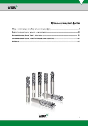 Каталог Widia цельные концевые фрезы
- TABLE OF CONTENTS
- INDEXABLE MILLING
- 0º/90º SHOULDER MILLS
- 90° HIGH-SPEED CUTTING MILLS
- FACE MILLS
- HIGH-FEED MILLS
- COPY MILLS
- SOLID END MILLING
- HIGH-PERFORMANCE SOLID CARBIDE END MILLS
- GENERAL PURPOSE SOLID CARBIDE END MILLS
- HOLEMAKING
- SOLID CARBIDE DRILLS
- MODULAR DRILLS
- INDEXABLE DRILLS
- TAPPING
- TURNING
- HIGH-PERFORMANCE INSERTS
- GROOVING & CUT-OFF
- Informational Icons Guide
- Material Overview • DIN

Application Data • Series 4000 4010 • Metric
Side Milling (A) Recommended feed per tooth (fz = mm/th) for side milling (A). TiAlN and Slotting (B) For slotting (B), reduce fz by 20%. Cutting Speed
| A | B | — vc | D1 — Diameter | |
| Material | m/min |
| Group | ae ap ap | min | max | mm | 3,0 | 4,0 | 5,0 | 6,0 | 8,0 | 10,0 | 12,0 | 14,0 | 16,0 | 18,0 | 20,0 | |||
| 0 | Ap1 max 0,1 x D | 0,5 x D | 150 – | 200 | fz | 0,021 | 0,028 | 0,036 | 0,044 | 0,060 | 0,072 | 0,083 | 0,092 | 0,101 | 0,108 | 0,114 | ||
| 1 | Ap1 max 0,1 x D | 0,5 x D | 150 – | 200 | fz | 0,021 | 0,028 | 0,036 | 0,044 | 0,060 | 0,072 | 0,083 | 0,092 | 0,101 | 0,108 | 0,114 | ||
| P | 2 | Ap1 max 0,1 x D | 0,5 x D | 140 – | 190 | fz | 0,021 | 0,028 | 0,036 | 0,044 | 0,060 | 0,072 | 0,083 | 0,092 | 0,101 | 0,108 | 0,114 | |
| 3 | Ap1 max 0,1 x D | 0,5 x D | 120 – | 160 | fz | 0,017 | 0,023 | 0,030 | 0,036 | 0,050 | 0,061 | 0,070 | 0,079 | 0,087 | 0,095 | 0,101 | ||
| 4 | Ap1 max 0,1 x D | 0,5 x D | 90 | – | 150 | fz | 0,016 | 0,021 | 0,027 | 0,033 | 0,045 | 0,054 | 0,062 | 0,070 | 0,077 | 0,083 | 0,088 | |
| 1 | Ap1 max 0,1 x D | 0,5 x D | 90 | – | 115 | fz | 0,017 | 0,023 | 0,030 | 0,036 | 0,050 | 0,061 | 0,070 | 0,079 | 0,087 | 0,095 | 0,101 | |
| M | ||||||||||||||||||
| 2 | Ap1 max 0,1 x D | 0,5 x D | 60 | – | 80 | fz | 0,014 | 0,019 | 0,024 | 0,029 | 0,040 | 0,048 | 0,056 | 0,063 | 0,070 | 0,076 | 0,081 | |
| 1 | Ap1 max 0,1 x D | 0,5 x D | 120 – | 150 | fz | 0,021 | 0,028 | 0,036 | 0,044 | 0,060 | 0,072 | 0,083 | 0,092 | 0,101 | 0,108 | 0,114 | ||
| K | ||||||||||||||||||
| 2 | Ap1 max 0,1 x D | 0,5 x D | 110 – | 140 | fz | 0,017 | 0,023 | 0,030 | 0,036 | 0,050 | 0,061 | 0,070 | 0,079 | 0,087 | 0,095 | 0,101 |
NOTE: Lower value of cutting speed is used for high stock removal applications or for higher hardness (machinability) within group. Higher value of cutting speed is used for finishing applications or for lower hardness (machinability) within group. Above parameters are based on ideal conditions. For smaller taper machining centres, please adjust parameters accordingly on >12mm diameters.
Application Data • Series D010 • Metric
| Side Milling (A) | TiAlN | Recommended feed per tooth (fz = mm/th) for side milling (A). | |
| Cutting Speed |
| A | — vc | D1 — Diameter | |
| Material | m/min |
| Group | ae ap min | max | mm | 3,0 | 4,0 | 5,0 | 6,0 | 8,0 | 10,0 | 12,0 | 14,0 | 16,0 | 18,0 | 20,0 | |||
| 0 | Ap1 max 0,1 x D | 150 | – | 200 | fz | 0,021 | 0,028 | 0,036 | 0,044 | 0,060 | 0,072 | 0,083 | 0,092 | 0,101 | 0,108 | 0,114 | |
| 1 | Ap1 max 0,1 x D | 150 | – | 200 | fz | 0,021 | 0,028 | 0,036 | 0,044 | 0,060 | 0,072 | 0,083 | 0,092 | 0,101 | 0,108 | 0,114 | |
| P | 2 | Ap1 max 0,1 x D | 140 | – | 190 | fz | 0,021 | 0,028 | 0,036 | 0,044 | 0,060 | 0,072 | 0,083 | 0,092 | 0,101 | 0,108 | 0,114 |
| 3 | Ap1 max 0,1 x D | 120 | – | 160 | fz | 0,017 | 0,023 | 0,030 | 0,036 | 0,050 | 0,061 | 0,070 | 0,079 | 0,087 | 0,095 | 0,101 | |
| 4 | Ap1 max 0,1 x D | 90 | – | 150 | fz | 0,016 | 0,021 | 0,027 | 0,033 | 0,045 | 0,054 | 0,062 | 0,070 | 0,077 | 0,083 | 0,088 | |
| 1 | Ap1 max 0,1 x D | 90 | – | 115 | fz | 0,017 | 0,023 | 0,030 | 0,036 | 0,050 | 0,061 | 0,070 | 0,079 | 0,087 | 0,095 | 0,101 | |
| M | |||||||||||||||||
| 2 | Ap1 max 0,1 x D | 60 | – | 80 | fz | 0,014 | 0,019 | 0,024 | 0,029 | 0,040 | 0,048 | 0,056 | 0,063 | 0,070 | 0,076 | 0,081 | |
| 1 | Ap1 max 0,1 x D | 120 | – | 150 | fz | 0,021 | 0,028 | 0,036 | 0,044 | 0,060 | 0,072 | 0,083 | 0,092 | 0,101 | 0,108 | 0,114 | |
| K | |||||||||||||||||
| 2 | Ap1 max 0,1 x D | 110 | – | 140 | fz | 0,017 | 0,023 | 0,030 | 0,036 | 0,050 | 0,061 | 0,070 | 0,079 | 0,087 | 0,095 | 0,101 |
NOTE: Lower value of cutting speed is used for high stock removal applications or for higher hardness (machinability) within group. Higher value of cutting speed is used for finishing applications or for lower hardness (machinability) within group. Above parameters are based on ideal conditions. For smaller taper machining centres, please adjust parameters accordingly on >12mm diameters.
= ALL-STAR PORTFOLIO PRODUCT. ALL-STAR PRODUCTS ARE
PROVEN SOLUTIONS THAT ARE ALWAYS AVAILABLE.