Каталог TooTool техническая информация 2 - страница 159
Навигация

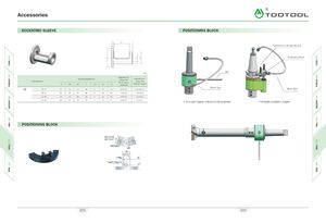
Accessories A\ ECCENTRIC SLEEVE POSITIONING BLOCK L3 Connected to the spindle end ’'o s- s Positioning Block mm Designation D Designation(mm)D1D2LLI L2 L3 adjustmentrange forProcessingdiameter adjustmentrange forCenter height CE 20-25 41 20 25 48 6 11 33 +0.4-0.2 +0.2-0.15 Water Pipe 25-32 49 25 32 60 6 11 45 +0.4-0.2 +0.2-0.15 32-40 58 32 40 65 6 11 50 +0.4-0.2 +0.2-0.15 40-50 68 40 50 76 6 11 61 +0.4-0.2 +0.2-0.2 X. Schematic diagram of Morse handle installation X. BT handle installation diagram POSITIONING BLOCK (§) #40 D=25 / #50 D=27 9 !§)' ^ bolt holes , 06 *— 35—» I8.2±0.1 o-ringRc(PT) 3,'8orV4 ^" i '1 9]21 iJ 673 674
 Каталог TooTool техническая информация 1
 Общий каталог TooTool
 Каталог TooTool монолитные фрезы