Каталог TooTool техническая информация 1 - страница 39
Навигация
 Общий каталог TooTool
 Каталог TooTool монолитные фрезы
 Каталог TooTool техническая информация 2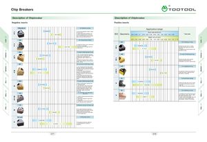
Chip Breakers A\
0
Description of Chipbreaker Description of Chipbreaker
Negative inserts Positive inserts
Standard For General cutting
Application range
0.2- 0.5
P •With broad applied range for steel
and cast iron. feed rate ( mm / rev )
K •High cutting edge hardness, low
ISO Geometry Features
-
5.0 15.0 cutting resistance force, eay chip - 0.04 0.063 0.1 0.16 0.25 0.40 0.63 1.00 1.60 2.50 4.00 6.30
flow. Combined with more abrasive
grade can get better efficiency.
depth of cut ( mm )
0.10 0.16 0.25 0.40 0.63 1.00 1.60 2.50 4.00 6.30 10.00 11.6 13 15
For Heavy duty cutting
HF For finishing turning
0.3- 1.0
P • Sutable for haevy duty cutting due
K to strong cutting edge . 0.05 -0.3
3.0- 15.0 • Wide chip control range with low P
I I I I I I I
• Excellent chip control in steel,
stainless steel , grey and nodular
cutting force. M cast -iron.
0.1- 2.0
• Suitable for both boring and outer
diameter turning.
For semi-finishing machining
For semi -finishing turning
0.15 - 0.5 • First recommendation for medium
cutting of carbon steel and alloy steel
P •Alternative chipbreaker for
M I I finishing and light cutting of cast
0.2 -0.5
0.2 - 6.0 iron . P
• Suitable for feneral field. Positive M 1.0-4.0
• Excellent chip control at wide
range of cutting conditions
edge shape of blade, performance of
sharp cutting. • Suitable for stainless steel cutting.
For stainless finishing turning
semi- finishing to finishing under For roughing turning
•
with high efficiency high feed rate is
adopted under the condition of small
0.05 - 0.3
cutting depth. P 0.3 -0.7
M I I I I I I I • M
Due to the latest chipbreaker • suitable for internal and external
s 0.1-1.0
design, it can obtain good chip
K 3.0-7.0
roughing of steel , stainless steel
control and good machining surface and cast iron material.
accuracy.
• The extremely sharp edge and
high rake angel design especially is
suitable for stainless steel & softy
steel. AL For Aluminum cutting
ISL
BM For semi-finishing machining 0.03- 0.4
• Has a wide range of applications N I I I I I I I I I • Wide available chip control range
0.1- 0.3 for stainless steel.
from medium-finishing to medium
roughing.
-
0.1-4.0
M I I • Can effictively solve machining
difficulties such as chip breaking • High speed of finishing operation.
0.5-1.5 and sticking phenomenon in the
stainless steel processing, which
can obtain higher machining For finishing turning
efficency.
For Light -alloy, Stainless -steel
0.03 - 0.3
machining • Suitable for finishing machining of
s I I I I I I heat resistance alloy, titanium alloy
and other aerospace parts.
M • Sharp cutting edge generates low 0.06 - 1.7 •Loght cutting chip breaker with low
cutting force.
s • Specially designed tough main cutting force, high reliability and
N cutting edge.
.
universality Problem free cutting.
• Sutable for cutting of low carbon
steel , stainless steel, aluminum.
HS For Medium cutting of stainless steel
0.1- 0.4 • Exclusive design for stainless
M steel cutting provide longer tool life .
1.0-4.0
•Wear resistance have been
reinforced through high rake angle
of chip breaker land.
No slot ForRoughing turning
K > 0.05 - 0.6
I I I I I I1 •For grey and nodular cast-iron.
0.3-12.0 •Broad application range for
roughing.
077 078
0
Description of Chipbreaker Description of Chipbreaker
Negative inserts Positive inserts
Standard For General cutting
Application range
0.2- 0.5
P •With broad applied range for steel
and cast iron. feed rate ( mm / rev )
K •High cutting edge hardness, low
ISO Geometry Features
-
5.0 15.0 cutting resistance force, eay chip - 0.04 0.063 0.1 0.16 0.25 0.40 0.63 1.00 1.60 2.50 4.00 6.30
flow. Combined with more abrasive
grade can get better efficiency.
depth of cut ( mm )
0.10 0.16 0.25 0.40 0.63 1.00 1.60 2.50 4.00 6.30 10.00 11.6 13 15
For Heavy duty cutting
HF For finishing turning
0.3- 1.0
P • Sutable for haevy duty cutting due
K to strong cutting edge . 0.05 -0.3
3.0- 15.0 • Wide chip control range with low P
I I I I I I I
• Excellent chip control in steel,
stainless steel , grey and nodular
cutting force. M cast -iron.
0.1- 2.0
• Suitable for both boring and outer
diameter turning.
For semi-finishing machining
For semi -finishing turning
0.15 - 0.5 • First recommendation for medium
cutting of carbon steel and alloy steel
P •Alternative chipbreaker for
M I I finishing and light cutting of cast
0.2 -0.5
0.2 - 6.0 iron . P
• Suitable for feneral field. Positive M 1.0-4.0
• Excellent chip control at wide
range of cutting conditions
edge shape of blade, performance of
sharp cutting. • Suitable for stainless steel cutting.
For stainless finishing turning
semi- finishing to finishing under For roughing turning
•
with high efficiency high feed rate is
adopted under the condition of small
0.05 - 0.3
cutting depth. P 0.3 -0.7
M I I I I I I I • M
Due to the latest chipbreaker • suitable for internal and external
s 0.1-1.0
design, it can obtain good chip
K 3.0-7.0
roughing of steel , stainless steel
control and good machining surface and cast iron material.
accuracy.
• The extremely sharp edge and
high rake angel design especially is
suitable for stainless steel & softy
steel. AL For Aluminum cutting
ISL
BM For semi-finishing machining 0.03- 0.4
• Has a wide range of applications N I I I I I I I I I • Wide available chip control range
0.1- 0.3 for stainless steel.
from medium-finishing to medium
roughing.
-
0.1-4.0
M I I • Can effictively solve machining
difficulties such as chip breaking • High speed of finishing operation.
0.5-1.5 and sticking phenomenon in the
stainless steel processing, which
can obtain higher machining For finishing turning
efficency.
For Light -alloy, Stainless -steel
0.03 - 0.3
machining • Suitable for finishing machining of
s I I I I I I heat resistance alloy, titanium alloy
and other aerospace parts.
M • Sharp cutting edge generates low 0.06 - 1.7 •Loght cutting chip breaker with low
cutting force.
s • Specially designed tough main cutting force, high reliability and
N cutting edge.
.
universality Problem free cutting.
• Sutable for cutting of low carbon
steel , stainless steel, aluminum.
HS For Medium cutting of stainless steel
0.1- 0.4 • Exclusive design for stainless
M steel cutting provide longer tool life .
1.0-4.0
•Wear resistance have been
reinforced through high rake angle
of chip breaker land.
No slot ForRoughing turning
K > 0.05 - 0.6
I I I I I I1 •For grey and nodular cast-iron.
0.3-12.0 •Broad application range for
roughing.
077 078