Общий каталог Sumitomo 2019 - 2020 - страница 534
Навигация
 Каталог Sumitomo запасные части
 Каталог Sumitomo сплавы и режимы
 Техническая информация Sumitomo
 Каталог Sumitomo пластины с алмазными вставками Sumidia
 Каталог Sumitomo специальные торцевые фрезы
 Общий каталог Sumitomo 2018 - 2019
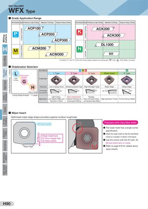
Milling CuttersFace MillingShoulde rMillingHigh FeedMulti-PurposeRadiusR / 3DProfilingGroove /T-SlotChamferingNon-ferrousMetalHigh-speedCast Iron GoodCutting Edge Sharpness Coated CarbideCoated Carbide 0.15mm Coated CarbideCoated CarbideCarbide SEC-WaveMill WFX Type ■ Grade Application Range Work Material Grade Finishing to Light Cutting Medium Cutting Rough to Heavy Cutting Work Material Grade Finishing to Light Cutting Medium Cutting Rough to Heavy Cutting ACP100 C ACK200 C Steel P ACP200 Cast Iron P ACK300 P ACP300 P DL1000 H ACM200 C Non-Ferrous Metal Stainless Steel P ACM300 H1 The letters "C" and "P" at the end of each grade indicate the coating type. C : CVD, P : PVD, Blank: Uncoated ■ Chipbreaker Selection Work Material P M K N ↑ L General-purpose L Type G Type H Type Wiper Insert S Type (Standard) Light Chipbreaker Cutting G H Features Low Cutting Force General-purpose Type High Strength Type Wiper Edge Sharp Edge Cutting Edge 20 ° 15°Heavy CuttingCross Section 10° 15° 25° Cutting Edge Strength → Large Light Cutting, Main Chipbreaker Roughing, Applications Low Rigidity Milling and General Purpose to Heavy Interrupted Cutting High-precision Finish For Non-Ferrous Metals Reduction of Burrs Interrupted Milling and Hardened Steel Milling ■ Wiper Insert Optimised wiper edge shape provides superior surface roughness. M Class Inserts (1) Precautions when Using Wiper Inserts ● The wiper insert has a single corner speci cation. ● Attach the wiper insert so that the chamfered Wiper inserts are0.15mm longer than corner is in location (1) shown in the gure. M Class inserts ● Use the corner with the ID mark. (2) (2) (08-size inserts have no marks) Wiper Edge ● Refer to page N19 for details about wiper inserts. H90