Общий каталог Sumitomo 2019 - 2020 - страница 366
Навигация
 Каталог Sumitomo запасные части
 Каталог Sumitomo сплавы и режимы
 Техническая информация Sumitomo
 Каталог Sumitomo пластины с алмазными вставками Sumidia
 Каталог Sumitomo специальные торцевые фрезы
 Общий каталог Sumitomo 2018 - 2019
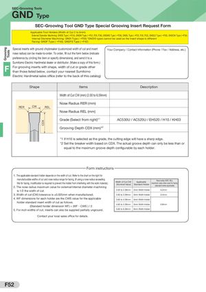
Grooving Tools CDX SEC-Grooving Tools GND Type SEC-Grooving Tool GND Type Special Grooving Insert Request Form Applicable Tool Holders (Width of Cut 2 to 6mm) External Diameter Machining: GNDS Type (→F24), GNDM Type (→F22, F26, F28), GNDMS Type (→F26), GNDL Type (→F22, F30, F32), GNDLS Type (→F30), GNDCM Type (→F34) Internal Diameter Machining: GNDI Type (→F50) *GNDIS types cannot be used as the insert shape is different Facing: GNDF Type (→F40), GNDFS Type (→F42) Special inserts with ground chipbreaker (customized width of cut and insert Your Company / Contact Information (Phone / Fax / Address, etc.) nose radius) can be made-to-order. To order, fill out the form below (indicate preference by circling the item or specify dimensions), and send it to a Sumitomo Electric Hardmetal dealer or distributor. (Make a copy of this form.) F For grooving inserts with shape, width of cut or grade otherthan those listed below, contact your nearest Sumitomo Electric Hardmetal sales office (refer to the back of this catalog) Shape Items Description Width of Cut CW (mm) (2.00 to 6.59mm) Nose Radius RER (mm) RER CW REL Nose Radius REL (mm) Grade (Select from right)*1 AC530U / AC520U / EH520 / H10 / KH03 Grooving Depth CDX (mm)*2 *1 If H10 is selected as the grade, the cutting edge will have a sharp edge. *2 Set the breaker width based on CDX. The actual groove depth can only be less than or equal to the maximum groove depth configurable by each holder. Form instructions 1. The applicable standard holder depends on the width of cut. Refer to the chart on the right for manufacturable widths of cut and nose radius range for facing. (If using a nose radius exceedingthis for facing, modification is required to prevent the holder from interfering with the work material.)2. The nose radius maximum value for external/internal diameter machiningWidth of Cut CW(Nominal Value)ApplicableStandard HolderNose radius (RER, REL)maximum value when used for facing(standard holder applicable) is 1/2 the width of cut. 2.00 to 2.59mm 2mm Width Holder 0.2mm 3. Width of cut (CW) tolerance is ±0.025mm when manufactured. 2.60 to 3.59mm 3mm Width Holder 0.4mm 4. WF dimensions for each holder are the CWS value for the applicable 3.60 to 4.59mm 4mm Width Holder holder standard insert width of cut as follows. (Standard holder dimension WF) + (WF - CWS ) / 2 4.60 to 5.59mm 5mm Width Holder 0.8mm 5. For inch widths of cut, inserts can also be supplied partially unground. 5.60 to 6.59mm 6mm Width Holder Contact your local sales office for details. F52