Общий каталог Sumitomo 2019 - 2020 - страница 1013
Навигация
 Каталог Sumitomo запасные части
 Каталог Sumitomo сплавы и режимы
 Техническая информация Sumitomo
 Каталог Sumitomo пластины с алмазными вставками Sumidia
 Каталог Sumitomo специальные торцевые фрезы
 Общий каталог Sumitomo 2018 - 2019
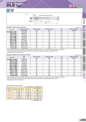
DC h8 118˚ DCON h8 OthersBrazedReamersIndexableIndexableInsert TypeHead TypeSolidDrilling Solid Carbide-Tipped Twist Drill DLS Type Cast Iron DuctileCast IronAluminumAlloyCopperAlloy Uncoated to Carbide Fig 1 PL Back Taper: 0.04 to 0.1/100 WBTHK LCF 5 OAL Straight Shank (For Cast Iron)Cat. No.Dia. (Shank Dia.) Flute LengthDC(DCON)LCF Overall LengthOAL TipPL Dimensions (mm)Web ThicknessWBTHKFigJ DLS 060 to 065 6.0 to 6.5 52 97 1.9 1.2 1 DLS 066 to 070 6.6 to 7.0 52 97 2.0 1.3 1 DLS 071 to 075 7.1 to 7.5 52 97 2.2 1.4 1 DLS 076 to 080 7.6 to 8.0 52 97 2.4 1.5 1 DLS 081 to 085 8.1 to 8.5 62 112 2.5 1.5 1 DLS 086 to 090 8.6 to 9.0 63 113 2.7 1.6 1 DLS 091 to 095 9.1 to 9.5 63 113 2.8 1.7 1 DLS 096 to 100 9.6 to 10.0 63 113 3.0 1.8 1 DLS 101 to 105 10.1 to 10.5 63 128 3.1 1.8 1 DLS 106 to 110 10.6 to 11.0 63 128 3.2 1.9 1 DLS 111 to 115 11.1 to 11.5 63 128 3.4 2.0 1 DLS 116 to 120 11.6 to 12.0 64 129 3.6 2.0 1 · Ordering numbers should be handled according to this example: ø10.5mm drill → DLS105. Please also advise work material. · Tang type drills (J/K) can be made to order if dimensions are included. Please advise tang dimensions J and K. · Helix angle 28°, flute width ratio 1.2:1. Straight Shank (For Aluminum Alloy) Dimensions (mm) Cat. No. Dia.DC Flute Length Overall LengthLCFOAL TipPL Web ThicknessWBTHK Fig DLS 060A to 065A 6.0 to 6.5 52 97 1.9 1.2 1 DLS 066A to 070A 6.6 to 7.0 52 97 2.0 1.3 1 DLS 071A to 075A 7.1 to 7.5 52 97 2.2 1.4 1 DLS 076A to 080A 7.6 to 8.0 52 97 2.4 1.5 1 DLS 081A to 085A 8.1 to 8.5 62 112 2.5 1.5 1 DLS 086A to 090A 8.6 to 9.0 63 113 2.7 1.6 1 DLS 091A to 095A 9.1 to 9.5 63 113 2.8 1.7 1 DLS 096A to 100A 9.6 to 10.0 63 113 3.0 1.8 1 DLS 101A to 105A 10.1 to 10.5 63 128 3.1 1.8 1 DLS 106A to 110A 10.6 to 11.0 63 128 3.2 1.9 1 DLS 111A to 115A 11.1 to 11.5 63 128 3.4 2.0 1 DLS 116A to 120A 11.6 to 12.0 64 129 3.6 2.0 1 · Ordering numbers should be handled according to this example: ø7.6mm drill → DLS076A. Please also advise work material. · Tang type drills (J/K) can be made to order if dimensions are included. Please advise tang dimensions J and K. · Helix angle 28°, flute width ratio 1.2:1. Recommended Cutting Conditions (vc: Cutting Speed (m/min), f: Feed Rate (mm/rev)) Dia. DC(mm)Conditions Ductile Cast Iron Cast Iron Non-FerrousAlloy ø10.0 vc 20 - 35 - 55 20 - 40 - 60 50 - 100 - 150 f 0.2 - 0.3 - 0.4 0.2 - 0.3 - 0.4 0.1 - 0.15 - 0.2 ø15.0 vc 30 - 50 - 70 30 - 60 - 80 70 - 130 - 200 f 0.3 - 0.35 - 0.4 0.3 - 0.35 - 0.4 0.1 - 0.15 - 0.2 ø25.0 vc 50 - 60 - 90 50 - 75 - 100 100 - 150 - 250 f 0.3 - 0.35 - 0.45 0.3 - 0.4 - 0.5 0.1 - 0.15 - 0.2 Min. - Optimum - Max. J153