Общий каталог Sumitomo 2018 - 2019 - страница 227
Навигация
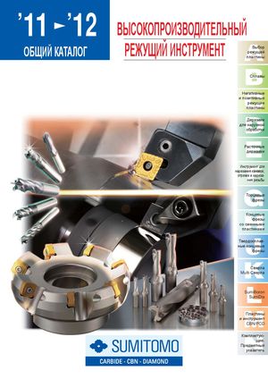 Общий каталог Sumitomo 2012
 Каталог Sumitomo резьбонарезной инструмент
 Каталог Sumitomo пластины с режущей кромкой-моноалмаз Sumicristal
 Каталог Sumitomo инструмент для обработки канавок
 Общий каталог Sumitomo 2019 - 2020
 Каталог Sumitomo запасные части
- Pages 3-6_CS6_EN_web
- A 1-20 insert selection EN_web
- B 1-14 grades_EN_web
- C01-17 inserts intro pages_EN_web
- C18-56 negative inserts_EN_web
- C57-86 positive inserts_EN_web
- D 1-46 tool holders_EN_web
- E 1-24 boring bars_EN_web
- F 1-48 grooving_thread tools_EN_web
- G 1-54 milling cutters_EN_web
- H 1-48 insert type endmills_EN_web
- J 1-24 new endmills_EN_web
- J 25-50 endmills_EN_web
- K 1-46 Multi-Drills_EN_web
- K 47-76 Multi-Drills_EN_web
- L 1-28 cbn_pcd grades_EN_web
- M 1-34 cbn_pcd inserts_EN_web
- M 35-56 SHM tools_EN_web
- N1-24 technical guidance_EN_web
- P 1-8 spare parts_neu_EN_web
- P 9-22 index_notes_EN_web

ISO-PSC Polygon Modular
GND Grooving System New PSC
General Features New grades and chipbreakers have been added to the already established GND grooving system with polygon shank and a flexible and economical cas-
sette system for inserts. An array of chipbreakers
improves the efficiency in chip control in various
applications such as grooving, turning, profiling and
cut-off. L
Advantages
GND inserts for soft grooving from 2,0 - 6,0 mm width
Expanded grade selection with 9 different chipbreakers
for a wide application range
Provides excellent chip control L
Achieves stable long tool life
Holder
| Cat. No. | R | L | Ø (mm) | F (mm) | L (mm) | Cap Screw | Tightening Torque (N·m) | Spanner |
| PSC40GM00R/L | l | l | 40 | 22 | 80 | |||
| PSC50GM00R/L | l | l | 50 | 27 | BFTX0619N | LT25 | ||
| PSC40GM90R/L | l | l | 40 | 42 | 52,5 | 7,5 | ||
| PSC50GM90R/L | l | l | 50 | 47 | 55,0 |
Cassette
| Cat. No. | R L | Grooving Width w (mm) | Grooving Depth (mm) | Inserts | Cap Screw | Tightening Torque (N·m) | Spanner |
| GNDCMR/L212 | l l | 2 | 12 | GCM□20□□-□□ | |||
| GNDCMR/L312 | l l | 3 | GCM□30□□-□□ | 5,0 | |||
| GNDCMR/L418 | l l | 4 | GCM□40□□-□□ | BX0512 | LH040 | ||
| GNDCMR/L518 | l l | 5 | 18 | GCM□50□□-□□ | 6,0 | ||
| GNDCMR/L618 | l l | 6 | GCM□60□□-□□ |
Identification Details - Polygon-Toolholder
PSC 40 - G M 00 R
Polygonshank Shank Diameter Series Symbol Application Style Holder Design
| (Ø D) | GND | External Multi-Purpose | 00 = Straight | R = Right | ||||
| 90 = L-Style | L = Left | |||||||
| Identification Details - Cassette | ||||||||
| GND | C | M | L | 3 | 12 | |||
| Series Symbol | Cassette | Application | Holder Design | Grooving Width | Max. |
GND External Multi-Purpose R = Right Grooving Depth
L = Left