Каталог Stellram токарный инструмент - страница 193
Навигация
 Каталог Stellram материалы и сплавы
 Каталог Stellram твердосплавные цельные фрезы
 Каталог Stellram фрез со сменными пластинами
 Каталог Stellram высокопроизводительные фрезерные системы
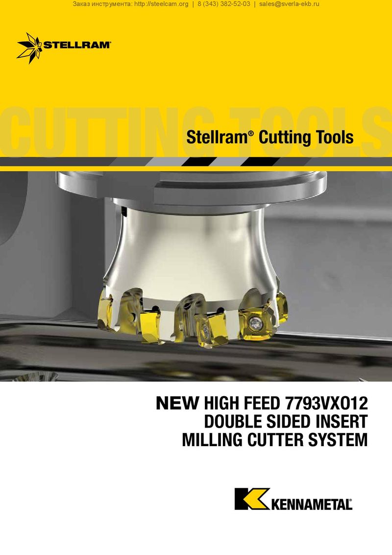 Каталог Stellram системы со сменными пластинами для фрезерования с высокими подачами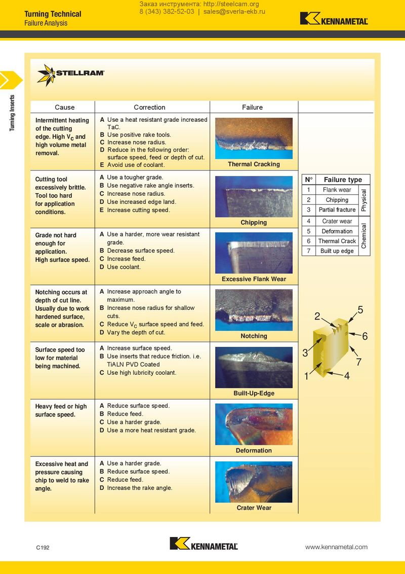
Failure Analysis
Cause Correction Failure
A Use a heat resistant grade increased Intermittent heating TaC. of the cutting
B Use positive rake tools. edge. High Vc and C Increase nose radius. high volume metal Reduce in the following order: D removal. surface speed, feed or depth of cut. E Avoid use of coolant. Thermal Cracking A Use a tougher grade.
| Cutting tool | N° | Failure type | |
| B Use negative rake angle inserts. | |||
| excessively brittle. | 1 | Flank wear | |
| C Increase nose radius. | |||
| Tool too hard | Chipping | ||
| D Use increased edge land. | 2 | ||
| for application | |||
| E Increase cutting speed. | 3 | Partial fracture | |
| conditions. | |||
| Chipping 4 | Crater wear | ||
| Use a harder, more wear resistant 5 | Deformation | ||
| Grade not hard | A | ||
| grade. 6 | Thermal Crack | ||
| enough for | |||
| application. | B Decrease surface speed. | 7 | Built up edge |
High surface speed. C Increase feed. D Use coolant. Excessive Flank Wear Notching occurs at A Increase approach angle to
depth of cut line. maximum.
Usually due to work B Increase nose radius for shallow 5
hardened surface, cuts. 2
scale or abrasion. C Reduce V surface speed and feed. c D Vary the depth of cut. 6 Notching
A Increase surface speed. Surface speed too 3 B Use inserts that reduce friction. i.e. low for material 7 TiALN PVD Coated being machined.
C Use high lubricity coolant. 1 4
Built-Up-Edge Heavy feed or high A Reduce surface speed. surface speed. B Reduce feed. C Use a harder grade. D Use a more heat resistant grade.
Deformation A Use a harder grade. Excessive heat and B Reduce surface speed. pressure causing C Reduce feed. chip to weld to rake D Increase the rake angle. angle.
Crater Wear