Каталог Stellram фрез со сменными пластинами - страница 181
Навигация
 Каталог Stellram твердосплавные цельные фрезы
 Каталог Stellram токарный инструмент
 Каталог Stellram системы со сменными пластинами для фрезерования с высокими подачами
 Каталог Stellram высокопроизводительные фрезерные системы
 Каталог Stellram материалы и сплавы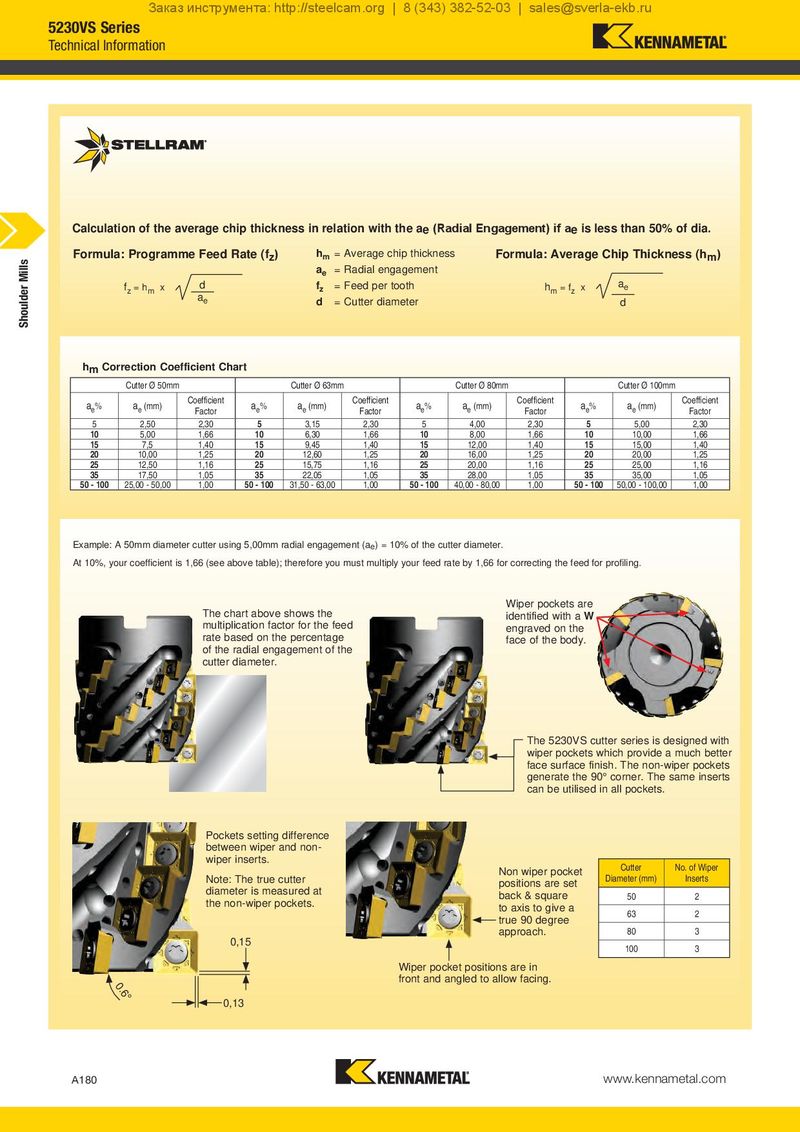
Calculation of the average chip thickness in relation with the ae (Radial Engagement) if ae is less than 50% of dia.
| Formula: Programme Feed Rate (f ) | h | = Average chip thickness | Formula: Average Chip Thickness (h | ) | |
| z | m | m | |||
| a = Radial engagement | |||||
| e |
| f | d | f = Feed per tooth | h | a | |||
| = h | x | z | = f x | e | |||
| z | m | m | z | ||||
| a | |||||||
| e | d = Cutter diameter | d |
hm Correction Coefficient Chart
Cutter Ø 50mm Cutter Ø 63mm Cutter Ø 80mm Cutter Ø 100mm
| a | a | Coefficient | a | a | Coefficient | a | a | Coefficient | a | a | Coefficient |
| e% | e (mm) | Factor | e% | e (mm) | Factor | e% | e (mm) | Factor | e% | e (mm) | Factor |
| 5 | 2,50 | 2,30 | 5 | 3,15 | 2,30 | 5 | 4,00 | 2,30 | 5 | 5,00 | 2,30 |
| 10 | 5,00 | 1,66 | 10 | 6,30 | 1,66 | 10 | 8,00 | 1,66 | 10 | 10,00 | 1,66 |
| 15 | 7,5 | 1,40 | 15 | 9,45 | 1,40 | 15 | 12,00 | 1,40 | 15 | 15,00 | 1,40 |
| 20 | 10,00 | 1,25 | 20 | 12,60 | 1,25 | 20 | 16,00 | 1,25 | 20 | 20,00 | 1,25 |
| 25 | 12,50 | 1,16 | 25 | 15,75 | 1,16 | 25 | 20,00 | 1,16 | 25 | 25,00 | 1,16 |
| 35 | 17,50 | 1,05 | 35 | 22,05 | 1,05 | 35 | 28,00 | 1,05 | 35 | 35,00 | 1,05 |
| 50 - 100 | 25,00 - 50,00 | 1,00 | 50 - 100 | 31,50 - 63,00 | 1,00 | 50 - 100 | 40,00 - 80,00 | 1,00 | 50 - 100 | 50,00 - 100,00 | 1,00 |
Example: A 50mm diameter cutter using 5,00mm radial engagement (ae) = 10% of the cutter diameter. At 10%, your coefficient is 1,66 (see above table); therefore you must multiply your feed rate by 1,66 for correcting the feed for profiling.
Wiper pockets are
The chart above shows the identified with a W
multiplication factor for the feed engraved on the
rate based on the percentage face of the body.
of the radial engagement of the
cutter diameter.
The 5230VS cutter series is designed with
wiper pockets which provide a much better
face surface finish. The non-wiper pockets
generate the 90° corner. The same inserts
can be utilised in all pockets.
Pockets setting difference
between wiper and non-
wiper inserts.
Note: The true cutter
diameter is measured at
the non-wiper pockets.
0,15
0.6°
0,13
Cutter No. of Wiper
| Non wiper pocket | Diameter (mm) | Inserts |
| positions are set | ||
| back & square | 50 | 2 |
| to axis to give a | 63 | 2 |
| true 90 degree | ||
| approach. | 80 | 3 |
100 3 Wiper pocket positions are in front and angled to allow facing.