Общий каталог SGS 2021 - страница 24
Навигация
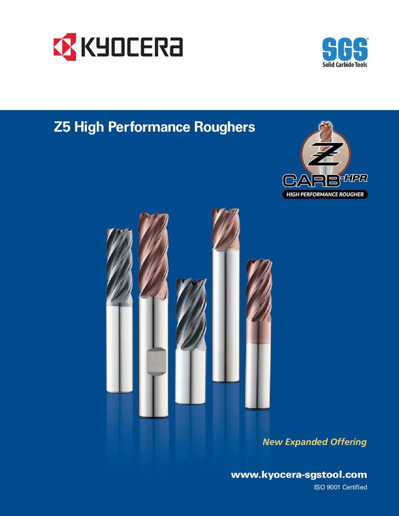 Каталог SGS высокопроизводительные черновые фрезы
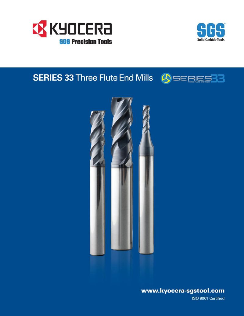 Каталог SGS фрезы для труднообрабатываемых материалов Series 33
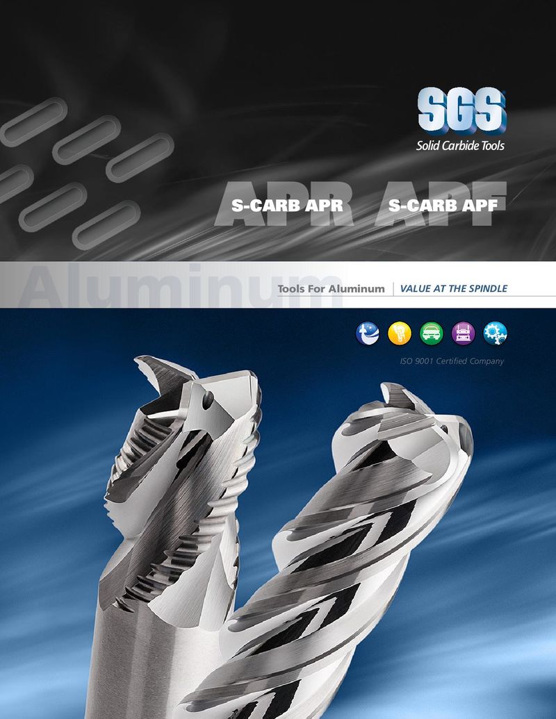 Каталог SGS фрезы для алюминия S-carb
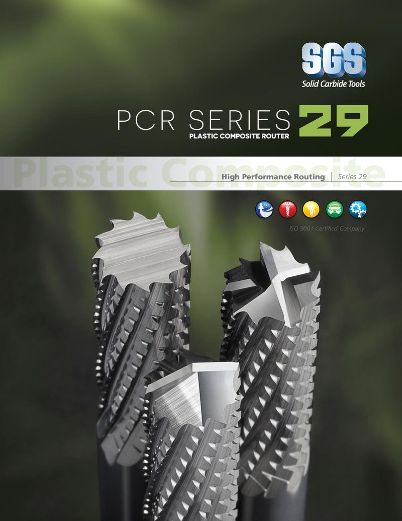 Каталог SGS фрезы для обработки пластика PCR series
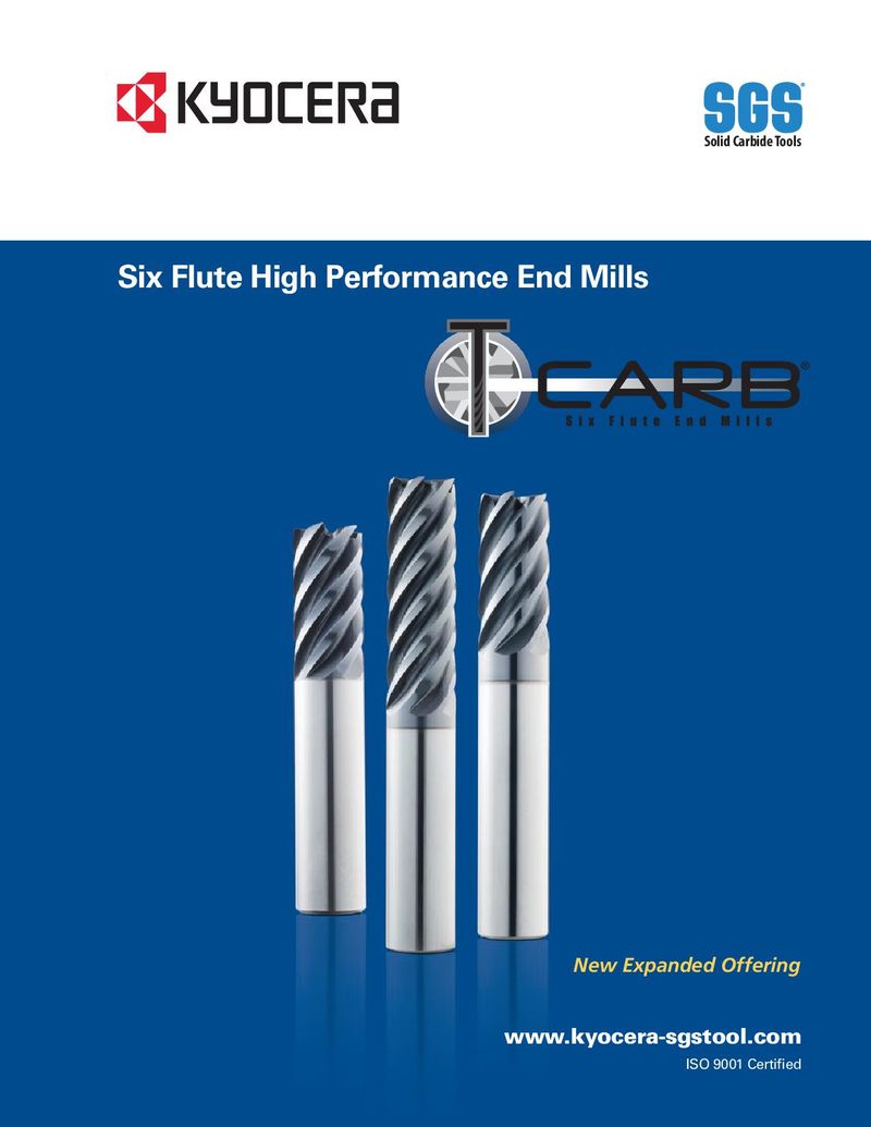 Каталог SGS шестизубые фрезы T-carb
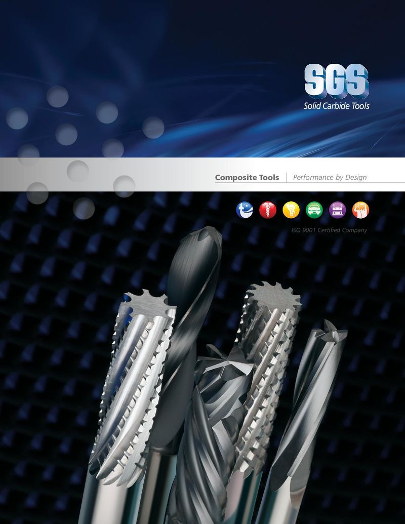 Каталог SGS монолитный инструмент из композитных материалов
END MILLING APPLICATION TIPS END MILLING APPLICATION TIPS END MILLING APPLICATION TIPS (See specific tool series for any additional tips).(See specific tool series for any additional tips).(See specific tool series for any additional tips). ToolTool Application Tips Tool Whenever possible, select an end mill with the largest diameter, shortest flute length,• Whenever possible, select an end mill with the largest diameter, shortest flute length,• Whenever possible, select an end mill with the largest diameter, shortest flute length, and shortest overall length for the best rigidity and shortest overall length for the best rigidity and shortest overall length for the best rigidity
- Long flute tools are not intended for pocketing, slotting, or heavy profiling – limit Rw to .02D• Long flute tools are not intended for pocketing, slotting, or heavy profiling – limit Rw to .02D• Long flute tools are not intended for pocketing, slotting, or heavy profiling – limit Rw to .02D
- High Performance tools minimize cycle time and extend tool life• High Performance tools minimize cycle time and extend tool life• High Performance tools minimize cycle time and extend tool life
Tool Whenever possible, select an end mill with the largest diameter, shortest flute length, and shortest overall length for the best rigidity Tool HoldersTool HoldersTool Holders Holders with adequate gripping pressure and TIR are required• Holders with adequate gripping pressure and TIR are required• Long flute tools are not intended for pocketing, slotting, or heavy profiling – limit Ae to .02D• Holders with adequate gripping pressure and TIR are required
- Stub holders or zero length collet style holders are recommended for heavy stock removal• Stub holders or zero length collet style holders are recommended for heavy stock removal• High Performance tools minimize cycle time and extend tool life• Stub holders or zero length collet style holders are recommended for heavy stock removal
- When using solid holders, hand ground screw flats are not recommended• When using solid holders, hand ground screw flats are not recommended• When using solid holders, hand ground screw flats are not recommended
Tool Holders Holders with adequate gripping pressure and TIR are required WorkpieceWorkpieceWorkpiece Secure clamping of the workpiece will reduce chatter and deflection• Secure clamping of the workpiece will reduce chatter and deflection• Stub holders or zero length collet style holders are recommended for heavy stock removal• Secure clamping of the workpiece will reduce chatter and deflection
- When using solid holders, hand ground screw flats are not recommended
MachineMachineMachine Spindle must be in optimum condition for precise TIR and maximum tool life• Spindle must be in optimum condition for precise TIR and maximum tool life• Spindle must be in optimum condition for precise TIR and maximum tool life Workpiece Sufficient horsepower is required to perform at recommended speeds and feeds• Sufficient horsepower is required to perform at recommended speeds and feeds• Secure clamping of the workpiece will reduce chatter and deflection• Sufficient horsepower is required to perform at recommended speeds and feeds
- Reduce rates for low power machines to prevent workpiece and / or tool damage• Reduce rates for low power machines to prevent workpiece and / or tool damage• Reduce rates for low power machines to prevent workpiece and / or tool damage
Machine Spindle must be in optimum condition for precise TIR and maximum tool life CoolantCoolantCoolant Avoid re-milling chips through use of air blast or liquid coolant as necessary• Avoid re-milling chips through use of air blast or liquid coolant as necessary• Sufficient horsepower is required to perform at recommended speeds and feeds• Avoid re-milling chips through use of air blast or liquid coolant as necessary
- Maintain clean coolant with appropriate concentration• Maintain clean coolant with appropriate concentration• Reduce rates for low power machines to prevent workpiece and / or tool damage• Maintain clean coolant with appropriate concentration
- General recommendations:• General recommendations:• General recommendations:
Coolant Avoid re-milling chips through use of air blast or liquid coolant as necessary –Water Soluble Oil or Air Blast: Tool Steels, Mold & Die Steels, Carbon or Alloy Steels –Water Soluble Oil or Air Blast: Tool Steels, Mold & Die Steels, Carbon or Alloy Steels –Water Soluble Oil or Air Blast: Tool Steels, Mold & Die Steels, Carbon or Alloy Steels
- Maintain clean coolant with appropriate concentration
–Water Soluble Oil: Stainless Steels, Titanium, High Temperature Alloys, Non-Ferrous Alloys –Water Soluble Oil: Stainless Steels, Titanium, High Temperature Alloys, Non-Ferrous Alloys –Water Soluble Oil: Stainless Steels, Titanium, High Temperature Alloys, Non-Ferrous Alloys
- General recommendations:
—Water Soluble Oil or Air Blast: Tool Steels, Mold & Die Steels, Carbon or Alloy Steels MethodsMethodsMethods Climb milling is generally preferred• Climb milling is generally preferred• Climb milling is generally preferred —Water Soluble Oil: Stainless Steels, Titanium, High Temperature Alloys, Non-Ferrous Alloys
- Attention to programming details, tool holders, TIR, balance, fixturing, etc. improve cutting tool• Attention to programming details, tool holders, TIR, balance, fixturing, etc. improve cutting tool• Attention to programming details, tool holders, TIR, balance, fixturing, etc. improve cutting tool
performance and extend tool life performance and extend tool life performance and extend tool life Methods Climb milling is generally preferred
- Attention to programming details, tool holders, TIR, balance, fixturing, etc. improve cutting tool performance and extend tool life
END MILLING GUIDELINEEND MILLING GUIDELINEEND MILLING GUIDELINE END MILLING GUIDELINE DD = cutting diameter L = cutting diameter LD = cutting diameter L = flute length = flute length = flute length 1 1 DC = cutting diameter APMX = flute length1222 Speeds and Feeds for Cut Types are based on Radial Width ( Rw ) and Axial Depth ( Ad )Speeds and Feeds for Cut Types are based on Radial Width ( Rw ) and Axial Depth ( Ad )Speeds and Feeds for Cut Types are based on Radial Width ( Ae ) and Axial Depth ( Ap )Speeds and Feeds for Cut Types are based on Radial Width ( Rw ) and Axial Depth ( Ad ) Reductions to Speeds and Feeds may be necessary when: Rw and Ad exceed recommendationsReductions to Speeds and Feeds may be necessary when: Rw and Ad exceed recommendationsReductions to Speeds and Feeds may be necessary when: Ae and Ap exceed recommendationsReductions to Speeds and Feeds may be necessary when: Rw and Ad exceed recommendations
- Using long flute or extended reach tools• Using long flute or extended reach tools• Using long flute or extended reach tools• Using long flute or extended reach tools
- Using long tool holders• Using long tool holders• Using long tool holders• Using long tool holders
- Machining materials harder than listed• Machining materials harder than listed• Machining materials harder than listed• Machining materials harder than listed
ENTRY METHODSENTRY METHODSENTRY METHODSENTRY METHODS
Pre-Drilled HolePre-Drilled HolePre-Drilled Hole Helical Helical Helical Straight Straight Straight PlungePlungePlunge
RampRampRamp RampRampRamp
Pre-drilling is the preferred entry Alternative methods are helical and straight ramping. High Plunge only in non-ferrous
Pre-drilling is the preferredPre-drilling is the preferredPre-drilling is the preferred Alternative methods are helical and straight ramping. Alternative methods are helical and straight ramping. Alternative methods are helical and straight ramping. Plunge only in non-ferrousPlunge only in non-ferrousPlunge only in non-ferrous
method for most applications. ramp angles require reduced feed. Lower ramp angles will and short-chipping materials
| entry method for mostentry method for mostentry method for most | High ramp angles require reduced feed. Lower ramp High ramp angles require reduced feed. Lower ramp High ramp angles require reduced feed. Lower ramp | and short-chipping materialsand short-chipping materialsand short-chipping materials | ||
| allow higher feed rates and extend tool life. Use slotting | using slotting speeds and | |||
| applications.applications.applications. | angles will allow higher feed rates and extend tool life. angles will allow higher feed rates and extend tool life. angles will allow higher feed rates and extend tool life. | using slotting speeds andusing slotting speeds andusing slotting speeds and |
speeds and feeds for ramp angles of 1° to 2°. Reduce feed to 25% slotting feeds. Use slotting speeds and feeds for ramp angles of 1° to 2°. Use slotting speeds and feeds for ramp angles of 1° to 2°. Use slotting speeds and feeds for ramp angles of 1° to 2°. 25% slotting feeds.25% slotting feeds.25% slotting feeds. 25% when ramp angles approach 6°. General purpose tools Reduce feed to 25% when ramp angles approach 6°. Reduce feed to 25% when ramp angles approach 6°. Reduce feed to 25% when ramp angles approach 6°.
and/or difficult to machine materials will require lower ramp General purpose tools and/or difficult to machine General purpose tools and/or difficult to machine General purpose tools and/or difficult to machine angles and reduced feed. materials will require lower ramp angles and reduced feed.materials will require lower ramp angles and reduced feed.materials will require lower ramp angles and reduced feed.