Общий каталог OSG 2018 - 2019 - страница 656
Навигация
 Общий каталог OSG русский
 Общий каталог Somta
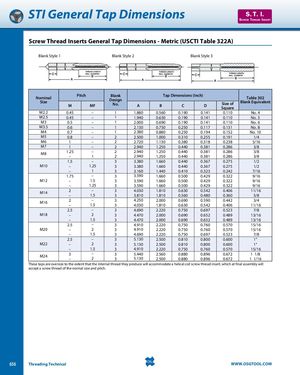
STI General Tap Dimensions S. T. I. SCREW THREAD INSERT Screw Thread Inserts General Tap Dimensions - Metric (USCTI Table 322A) Blank Style 1 Blank Style 2 Blank Style 3 NominalSIze Pitch BlankDesignM BLANK DMEFSIGN 1No.ATap Dimensions (Inch) Table 302BCDSize ofBlank EquivalentSquare M2.2 0.45 – 1 1.880 0.560 0.190 0.141 0.110 No. 4 M2.5 0.45 – 1 1.940 0.630 0.190 0.141 0.110 No. 5 M3 0.5 – 1 2.000 0.690 0.190 0.141 0.110 No. 6 M3.5 0.6 – 1 2.130 0.750 0.250 0.117 0.131 No. 8 M4 0.7 – 1 2.380 0.880 0.250 0.194 0.152 No. 10 M5 0.8 – 2 2.500 1.000 0.310 0.255 0.191 1/4 M6 1 – 2 2.720 1.130 0.380 0.318 0.238 5/16 M7 1 – 2 2.940 1.250 0.440 0.381 0.286 3/8 M8 1.25 ––1 2 2.940 1.250 0.440 0.381 0.28622.9401.2500.4400.3810.2863/83/8 1.5 – 3 3.380 1.660 0.440 0.367 0.275 1/2 M10 – 1.25 3 3.380 1.660 0.440 0.367 0.275 1/2 – 1 3 3.160 1.440 0.410 0.323 0.242 7/16 1.75 – 3 3.590 1.660 0.500 0.429 0.322 9/16 M12 – 1.5 3 3.590 1.660 0.500 0.429 0.322 9/16 – 1.25 3 3.590 1.660 0.500 0.429 0.322 9/16 M14 2 – 3 4.030 1.810 0.630 0.542 0.406 11/16–1.533.8101.8100.5600.4800.3605/8 M16 2 – 3 4.250 2.000 0.690 0.590 0.442 3/4–1.534.0301.8100.6300.5420.40611/16 2.5 – 3 4.690 2.220 0.750 0.697 0.523 7/8 M18 – 2 3 4.470 2.000 0.690 0.652 0.489 13/16 – 1.5 3 4.470 2.000 0.690 0.652 0.489 13/16 2.5 – 3 4.910 2.220 0.750 0.760 0.570 15/16 M20 – 2 3 4.910 2.220 0.750 0.760 0.570 15/16 – 1.5 3 4.690 2.220 0.750 0.697 0.523 7/8 2.5 – 3 5.130 2.500 0.810 0.800 0.600 1" M22 – 2 3 5.130 2.500 0.810 0.800 0.600 1" – 1.5 3 4.910 2.220 0.750 0.760 0.570 15/16 M24 3 ––2 3 5.440 2.560 0.880 0.896 0.672 1 1/835.1302.5000.8800.8960.6721 1/16 These taps are oversize to the extent that the internal thread they produce will accommodate a helical coil screw thread insert, which at final assembly will accept a screw thread of the normal size and pitch. 656 Threading Technical WWW.OSGTOOL.COM