Общий каталог Lamina Technologies 2019 - 2020 - страница 54
Навигация
 Общий каталог Lamina Technologies 2017 - 2018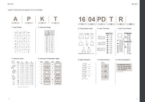
INSERT DESIGNATION (BASED ON ISO NORMS)
A P K T
| 1 | 22 | 33 | 44 | ||||
| 1. Insert Shape | 2. Clearance Angle | ||||||
| 85° | 82° | 80° | 55° |
16 04 PD T R
55 66 77 88 99 10
5. Cutting Edge Length 6. Insert Thickness 7. Insert Corner Radius
| A, B, K C, D, E, M, V H, O, P | Symbol mm | 1stletter (Milling) A = 45° | ||
| L L L L R S | S | 01 = 1.59 T1 = 1.98 02 = 2.38 03 = 3.18 | R 00 =Sharp corner or round insert (inch version) | 2ndletter (Milling) D E F P Z = 60° = 75° = 85° = 90° = other |
| S | T3 = 3.97 | M0 =Round insert (metric version) | A B = 3° = 5° | |
| L L L | 04 = 4.76 | 01 = 0.1 mm | C = 7° | |
| T W | S S | 05 = 5.56 06 = 6.35 07 = 7.94 | 02 04 08 12 16 = 0.2 mm = 0.4 mm = 0.8 mm = 1.2 mm = 1.6 mm | D E F G N = 15° = 20° = 25° = 30° = 0° |
| Disregarding any decimals e.g. 12,7 = 12 L L | 09 = 9.52 | etc | P Z = 11° = other |
3. Tolerance Class 4. Fixing and Chipbreaker Types
| 8. Edge Preparation | 9. Cutting Direction | 10. Internal Designation | |
| d (mm) |
| Symbol | D | M | S | Type | Symbol | Type | Symbol | ||
| m (mm) | Milling |
s (mm) A ± 0.025 ± 0.005 ± 0.025
A N F e.g. Application (Milling)
| m | C | ± 0.025 ± 0.013 | ± 0.025 | |||||
| R | - 45 = 45° Approach Angle | |||||||
| Ød | E | ± 0.025 ± 0.025 ± 0.025 | 70°- 90° | = 90° Approach Angle |
B P E - 90
| F | ± 0.013 ± 0.005 ± 0.025 | - HF = High Feed | ||
| m | G | ± 0.025 ± 0.025 ± 0.130 | L |
F R T Optional information
Ød H ± 0.013 ± 0.013 ± 0.025
m J* ± 0.05-0.15 ± 0.005 ± 0.025 40°- 60°
| G | T | S | ||
| K | N |
| * | ± 0.05-0.15 | ± 0.013 | ± 0.025 | |||
| L* | ± 0.025 | ± 0.025 | 70°- 90° | 40°- 60° | ||
| ± 0.05-0.15 | Optional information |
Ød H W Optional information
| M* | ± 0.05-0.15 ± 0.08-0.20 | ± 0.130 |
| N* | ± 0.05-0.15 ± 0.08-0.20 | ± 0.025 |
M X Special Design
s U* ± 0.08-0.25 ± 0.13-0.38 ± 0.130 LT 741 C W D016 2
* Depending on the insert size. - - /
| 1. Standard | 4. Internal Coolant | 5. Diameter | 6. # of Teeth | ||
| 2. Lamina Cutter | 3. Coupling |
104 Family Number 105
| LT - Metric | C - Cylindrical | D - No Internal | D016 = 16 mm | 2 = 2 teeth |
| RILT - Imperial | CL - Cylindrical Long | Coolant | D1000 = 1” |
W - Weldon W - Internal Coolant WL - Weldon Long M - Shell Mill S - Screw Coupling
FW - Long Edge