Основной каталог Kyocera 2016-2017 - страница 865
Навигация
 Каталог Kyocera фрезы MFH для высокоскоростной обработки
 Каталог Kyocera фрезы MEC высокопроизводительные концевые и торцевые фрезы
 Каталог микроинструмента Kyocera 2015-2016
 Каталог Kyocera высокоэффективные сверла со сменными пластинами DRV
 Каталог Kyocera пластины TQ для нарезания резьбы c прессованным стружколомом
 Каталог Kyocera высокопроизводительные модульные сверла DRA
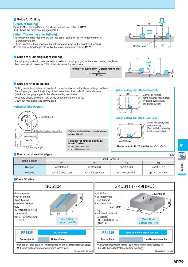
■ Guide for Drilling [Depth of Drilling] X Refer to Max. Cutting Depth (Pd) shown in the lower table of M178. (Pd Shows the maximum plunge depth.) [When Traversing after Drilling] ( 1 ) Reduce the table feed by 50% until the center core part (do not forget to grind) is completely cut off. (The internal cutting edge's radial rake angle is large in the negative direction) Center Core φD (2) The min. cutting length “X” for flat bottom surface is as follows M178. ■ Guide for Ramping (Slant Milling) L ・Ramping angle should be under αmax (Maximum ramping angle) in the above cutting conditions. ・Feed rate should be under 70% of the above cutting conditions. Formula of the cutting length “L” at Max. ramping angle αmax L= ap ap tan αmax ■ Guide for Helical milling ・Sinking depth (h) at helical milling should be under Max. ap in the above cutting conditions. [When cutting dia. φDh1≤φDh<φDh2] Ramping angle α (with trajectory of the center line of tool) should be under αmax (Maximum ramping angle) in the above cutting conditions. φDh Center core part ・Feed rate should be under 70% of the above cutting conditions. remains after machining. ・Down-cut machining is recommended. (Not removable with the same cutter) Helical Milling Factors φD φD (Cutting Dia.) [When cutting dia. φDh2≤φDh≤φDh3] φDh Center core part remains after machining. h (Sinking depth) (Removable by traversing φDs (Diameter of trajectory of tool's center line) φDs (How to find diameter of trajectory of tool's center line) with the same cutter) φDs=φDh-φD φDh (Machining Dia.) π×φDs Formula for sinking depth (h) φD α h=π×φDs×tanα M Ramping angle (h should be under ap) Please refer to M178 the list for φDh1~Dh3. (α should be under αmax) ■ Max. ap and usable edges (mm) Usable edges Insert Corner-R R4 R5 R6 R8 Milling 3 edges ap=2.0~4.0 ap=2.5~5.0 ap=3.0~6.0 ap=4.0~8.0 6 edges ap=2.0 Less than ap=2.5 Less than ap=3.0 Less than ap=4.0 Less than ■Case Studies SUS304 SKD61(47~49HRC) ・Nozzle parts ・Mold Part Slant face ・Vc=113m/min 35 ・Vc=125m/min ・fz=0.14mm/t ・fz=0.25mm/t 80 ・ap×ae=1.0×65mm 110 ・ap×ae=1.0 ~ ・Dry 2.0×10mm 230 ・MRX100R-12-9T-M ・Dry 380 (9 inserts) 65 ・MRX20-S20-08-2T ・RPGT1204M0ER-SM 4.5 times (2 inserts) (PR1535) ・RDGT0803M0ER-GM More than longer tool life (PR1525) double tool life PR1535 450 pcs/edge PR1525 2 pcs and more Stable tool life Conventional 100 pcs/edge Conventional 1 pc Unstable tool life ・High cost efficiency due to 4.5 times longer tool life and 1.5 times more insert edges. ・Conventional tool machined only 1 pc of workpiece due to unstable tool life, ・MRX prevented burr formation and improved surface finish. but MRX doubled the tool life with stable machining. (Evaluation by the user) (Evaluation by the user) M179