Основной каталог Kyocera 2016-2017 - страница 848
Навигация
 Каталог Kyocera фрезы MFH для высокоскоростной обработки
 Каталог Kyocera фрезы MEC высокопроизводительные концевые и торцевые фрезы
 Каталог микроинструмента Kyocera 2015-2016
 Каталог Kyocera высокоэффективные сверла со сменными пластинами DRV
 Каталог Kyocera пластины TQ для нарезания резьбы c прессованным стружколомом
 Каталог Kyocera высокопроизводительные модульные сверла DRA
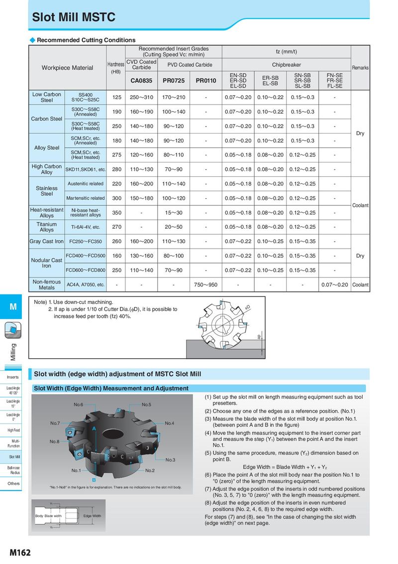
Slot Mill MSTC ◆ Recommended Cutting Conditions Recommended Insert Grades fz (mm/t) (Cutting Speed Vc: m/min) Hardness CVD Coated PVD Coated Carbide Chipbreaker Workpiece Material (HB) Carbide Remarks EN-SD ER-SB SN-SB FN-SE CA0835 PR0725 PR0110 ER-SD EL-SB SR-SB FR-SE EL-SD SL-SB FL-SE Low Carbon SS400 125 250~310 170~210 - 0.07~0.20 0.10~0.22 0.15~0.3 - Steel S10C~S25C S30C~S58C 190 160~190 100~140 - 0.07~0.20 0.10~0.22 0.15~0.3 - (Annealed) Carbon Steel S30C~S58C (Heat treated) 250 140~180 90~120 - 0.07~0.20 0.10~0.22 0.15~0.3 - Dry SCM,SCr, etc. 180 140~180 90~120 - 0.07~0.20 0.10~0.22 0.15~0.3 - (Annealed) Alloy Steel SCM,SCr, etc. 275 120~160 80~110 - 0.05~0.18 0.08~0.20 0.12~0.25 - (Heat treated) High Carbon SKD11,SKD61, etc. 280 110~130 70~90 - 0.05~0.18 0.08~0.20 0.12~0.25 - Alloy Stainless Austenitic related 220 160~200 110~140 - 0.05~0.18 0.08~0.20 0.12~0.25 - Steel Martensitic related 300 150~180 100~120 - 0.05~0.18 0.08~0.20 0.12~0.25 - Heat-resistant Coolant Ni-base heat- 350 - 15~30 - 0.05~0.18 0.08~0.20 0.12~0.25 - Alloys resistant alloys Titanium Ti-6Al-4V, etc. 270 - 20~50 - 0.05~0.18 0.08~0.20 0.12~0.25 - Alloys Gray Cast Iron FC250~FC350 260 160~200 110~130 - 0.07~0.22 0.10~0.25 0.15~0.35 - Nodular Cast FCD400~FCD500 160 130~160 80~100 - 0.07~0.22 0.10~0.25 0.15~0.35 - Dry Iron FCD600~FCD800 250 110~140 70~90 - 0.07~0.22 0.10~0.25 0.15~0.35 - Non-ferrous AC4A, A7050, etc. - - - 750~950 - - - 0.07~0.20 Coolant Metals M Note) 1. Use down-cut machining. 2. If ap is under 1/10 of Cutter Dia.(φD), it is possible to ID increase feed per tooth (fz) 40%. ap Milling Inserts Slot width (edge width) adjustment of MSTC Slot Mill Lead Angle Slot Width (Edge Width) Measurement and Adjustment 45°/20° (1) Set up the slot mill on length measuring equipment such as tool Lead Angle No.6 No.5 presetters. 15° Lead Angle (2) Choose any one of the edges as a reference position. (No.1) 0° (3) Measure the blade width of the slot mill body at position No.1. No.7 No.4 (between point A and B in the figure) High Feed A (4) Move the length measuring equipment to the insert corner part Multi- No.8 and measure the step (Y1) between the point A and the insert Function No.1. Slot Mill (5) Using the same procedure, measure (Y2) dimension based on No.3 point B. Ball-nose No.1 No.2 Edge Width = Blade Width + Y1 + Y2 Radius (6) Place the point A of the slot mill body near the position No.1 to Others B "0 (zero)" of the length measuring equipment. "No.1-No8" in the gure is for explanation. There are no indications on the slot mill body. (7) Adjust the edge position of the inserts in odd numbered positions (No. 3, 5, 7) to "0 (zero)" with the length measuring equipment. Y1 (8) Adjust the edge position of the inserts in even numbered positions (No. 2, 4, 6, 8) to the required edge width. Body Blade width Edge Width For steps (7) and (8), see "In the case of changing the slot width (edge width)" on next page. Y2 M162