Основной каталог Kyocera 2016-2017 - страница 846
Навигация
 Каталог Kyocera фрезы MFH для высокоскоростной обработки
 Каталог Kyocera фрезы MEC высокопроизводительные концевые и торцевые фрезы
 Каталог микроинструмента Kyocera 2015-2016
 Каталог Kyocera высокоэффективные сверла со сменными пластинами DRV
 Каталог Kyocera пластины TQ для нарезания резьбы c прессованным стружколомом
 Каталог Kyocera высокопроизводительные модульные сверла DRA
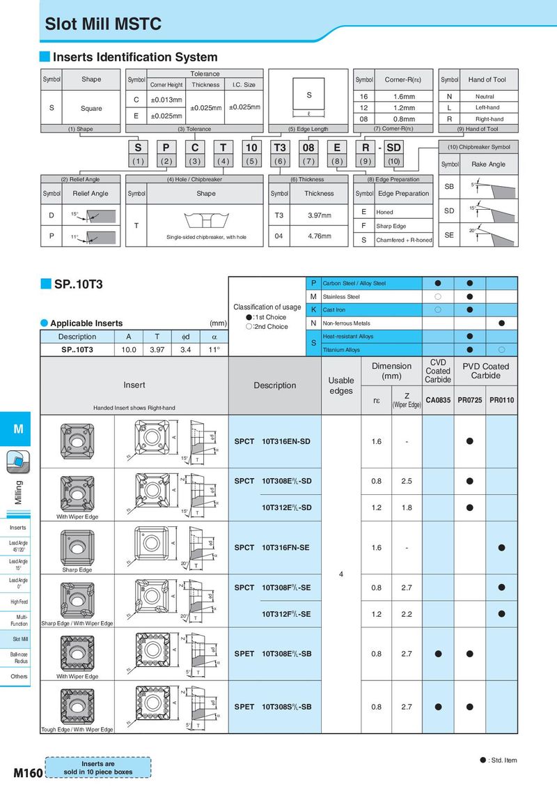
Slot Mill MSTC ■ Inserts Identification System Symbol Shape Tolerance Corner-R(rH) Symbol Corner Height Thickness I.C. Size Symbol Symbol Hand of Tool C ±0.013mm S 16 1.6mm N Neutral S Square ±0.025mm ±0.025mm 12 1.2mm L Left-hand E ±0.025mm ℓ 08 0.8mm R Right-hand (1) Shape (3) Tolerance (5) Edge Length (7) Corner-R(rH) (9) Hand of Tool S P C T 10 T3 08 E R - SD (10) Chipbreaker Symbol (1) (2) (3) (4) (5) (6) (7) (8) (9) (10) Symbol Rake Angle (2) Relief Angle (4) Hole / Chipbreaker (6) Thickness (8) Edge Preparation SB 5° Symbol Relief Angle Symbol Shape Symbol Thickness Symbol Edge Preparation E Honed SD 15° D 15° T3 3.97mm T F Sharp Edge 20° P 11° Single-sided chipbreaker, with hole 04 4.76mm S Chamfered + R-honed SE ■ SP..10T3 P Carbon Steel / Alloy Steel N N M Stainless Steel O N Classification of usage K Cast Iron O N ● Applicable Inserts (mm) ●:1st Choice N N ○:2nd Choice Non-ferrous Metals Description A T φd α Heat-resistant Alloys N SP..10T3 10.0 3.97 3.4 11° S Titanium Alloys N O Dimension CVD PVD Coated (mm) Coated Carbide Insert Description Usable Carbide edges Z rε (Wiper Edge) CA0835 PR0725 PR0110 Handed Insert shows Right-hand M Id A SPCT 10T316EN-SD 1.6 - N D rH 15° T Z SPCT 10T308E&-SD 0.8 2.5 N Milling A Id D 10T312E&-SD 1.2 1.8 N rH 15° T With Wiper Edge Inserts Lead Angle A Id 45°/20° SPCT 10T316FN-SE 1.6 - N D Lead Angle rH 20° T 15° Sharp Edge Lead Angle 4 0° Z SPCT 10T308F&-SE 0.8 2.7 N A Id High Feed D Multi- rH 20° T 10T312F&-SE 1.2 2.2 N Function Sharp Edge / With Wiper Edge Slot Mill Z A Id SPET 10T308E&-SB 0.8 2.7 N N Ball-nose Radius D rH 5° T Others With Wiper Edge Z A Id SPET 10T308S&-SB 0.8 2.7 N N D rH 5° T Tough Edge / With Wiper Edge Inserts are ● : Std. Item M160 sold in 10 piece boxes