Основной каталог Kyocera 2016-2017 - страница 841
Навигация
 Каталог Kyocera фрезы MFH для высокоскоростной обработки
 Каталог Kyocera фрезы MEC высокопроизводительные концевые и торцевые фрезы
 Каталог микроинструмента Kyocera 2015-2016
 Каталог Kyocera высокоэффективные сверла со сменными пластинами DRV
 Каталог Kyocera пластины TQ для нарезания резьбы c прессованным стружколомом
 Каталог Kyocera высокопроизводительные модульные сверла DRA
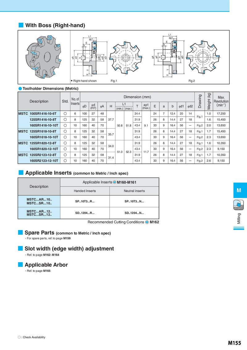
■ With Boss (Right-hand) L1 L1 ap1 ap1 E E a a IA Id b Id2 Id1 ID qA qd b qd1 qD T T H H ● Right-hand shown Fig.1 Fig.2 ● Toolholder Dimensions (Metric) No. of Dimension (mm) Drawing Weight (kg) Max. Description Std. Inserts L1 Revolution φD φd φA H T ap1 E a b φd1 φd2 (min-1) (H7) (min.) (max.) (max.) MSTC 100SR1416-10-6T O 6 100 27 48 24.4 24 7 12.4 20 14 1.0 17,250 Fig.1 125SR1416-10-8T O 8 125 32 58 37.7 31.9 26 8 14.4 27 18 1.6 15,450 160SR1416-10-10T O 10 160 40 70 50.8 51.8 43.4 9.1 30 9 16.4 56 - Fig.2 2.0 13,650 MSTC 125SR1618-10-8T O 8 125 32 58 31.9 26 8 14.4 27 18 Fig.1 1.7 15,450 35.7 160SR1618-10-10T O 10 160 40 70 43.4 30 9 16.4 56 - Fig.2 2.3 13,650 MSTC 125SR1820-12-8T O 8 125 32 58 31.9 26 8 14.4 27 18 Fig.1 1.6 10,350 34.0 160SR1820-12-10T O 10 160 40 70 43.4 30 9 16.4 56 - Fig.2 2.3 9,150 51.0 52.3 11.7 MSTC 125SR2123-12-8T O 8 125 32 58 31.9 26 8 14.4 27 18 Fig.1 1.7 10,350 31.4 160SR2123-12-10T O 10 160 40 70 43.4 30 9 16.4 56 - Fig.2 2.6 9,150 ■ Applicable Inserts (common to Metric / Inch spec) Applicable Inserts M160-M161 Description M Handed Inserts Neutral inserts MSTC...AR...10.. SP..10T3...R... SP..10T3...N... MSTC...SR...10.. MSTC...AR...12.. SD..1204...R... SD..1204...N... MSTC...SR...12.. Milling Recommended Cutting Conditions M162 ■ Spare Parts (common to Metric / Inch spec) ・For spare parts, ref. to page M159 ■ Slot width (edge width) adjustment ・Ref. to page M162~M164 ■ Applicable Arbor ・Ref. to page M165 ○ : Check Availability M155