Основной каталог Kyocera 2016-2017 - страница 790
Навигация
 Каталог Kyocera фрезы MFH для высокоскоростной обработки
 Каталог Kyocera фрезы MEC высокопроизводительные концевые и торцевые фрезы
 Каталог микроинструмента Kyocera 2015-2016
 Каталог Kyocera высокоэффективные сверла со сменными пластинами DRV
 Каталог Kyocera пластины TQ для нарезания резьбы c прессованным стружколомом
 Каталог Kyocera высокопроизводительные модульные сверла DRA
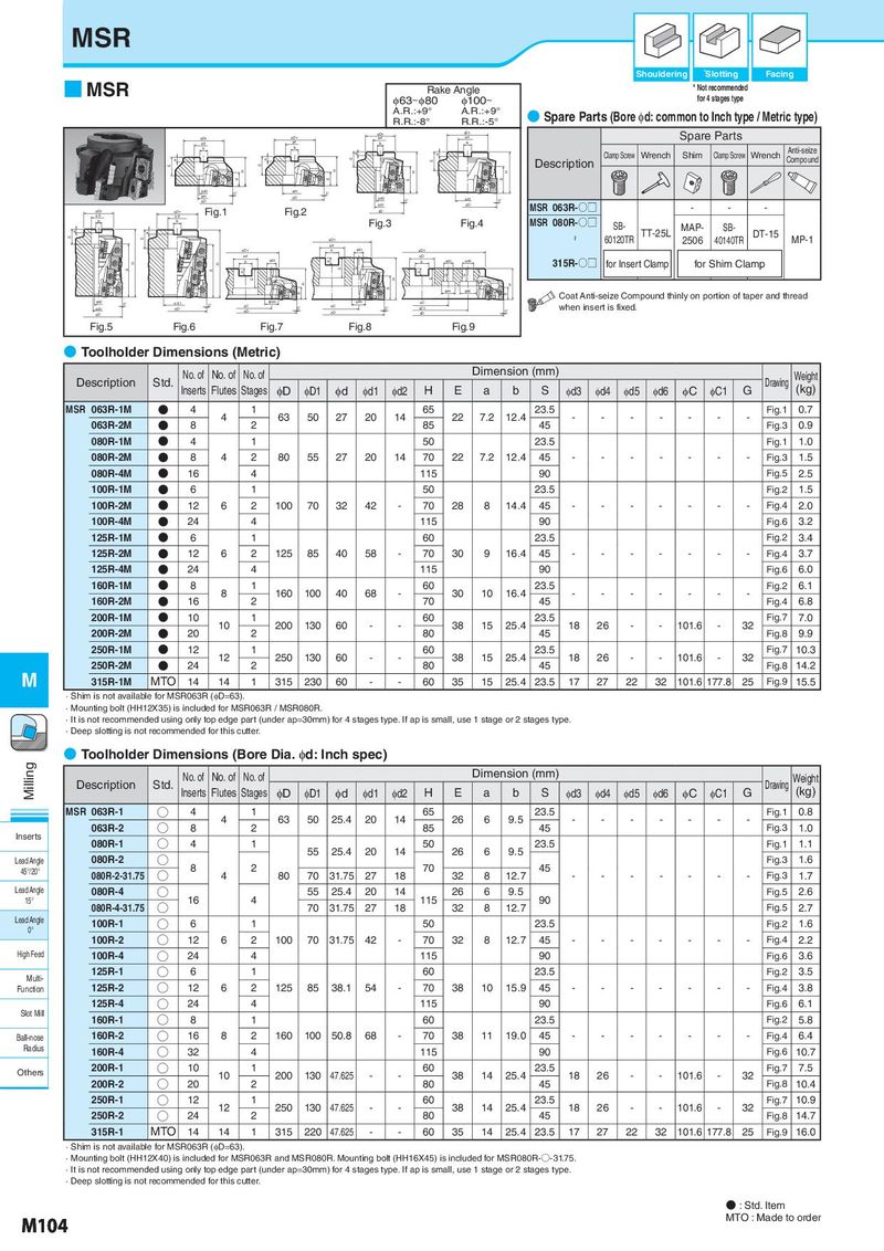
MSR Shouldering *Slotting Facing ■ MSR Rake Angle * Not recommended φ63~φ80 φ100~ for 4 stages type A.R.:+9° A.R.:+9° ● Spare Parts (Bore φd: common to Inch type / Metric type) R.R.:-8° R.R.:-5° ID1 ID1 Spare Parts ID1 ID1 Id Id Id Id b b b b Anti-seize a a Clamp Screw Wrench Shim Clamp Screw Wrench a a E E Description Compound E E H H H H S S S S Id2 0° Id1 0° Id1 ID Id2 Id1 ID 0° 0° Id1 ID MSR 063R-○□ - - - ID1 ID1 Fig.1 Fig.2 ID Id Id b b Fig.3 Fig.4 MSR 080R-○□ SB- a a TT-25L MAP- SB- DT-15 E E ~ 60120TR 2506 40140TR MP-1 ID1 Id ID1 b Id3 ID1 Id ID b Id3 a b Id3 Id5 315R-○□ for Insert Clamp for Shim Clamp H H S S E G a a G G E G H E H H S S Id4 Id6 S Coat Anti-seize Compound thinly on portion of taper and thread Id2 0° Id1 0° φd4 Id4 IC when insert is fixed. Id1 IC 0° IC 0° IC1 ID ID ID 0° ID ID Fig.5 Fig.6 Fig.7 Fig.8 Fig.9 ● Toolholder Dimensions (Metric) No. of No. of No. of Dimension (mm) Weight Description Std. Inserts Flutes Stages φD φD1 φd φd1 φd2 H E a b S φd3 φd4 φd5 φd6 φC φC1 G Drawing (kg) MSR 063R-1M N 4 4 1 63 50 27 20 14 65 22 7.2 12.4 23.5 - - - - - - - Fig.1 0.7 063R-2M N 8 2 85 45 Fig.3 0.9 080R-1M N 4 1 50 23.5 Fig.1 1.0 080R-2M N 8 4 2 80 55 27 20 14 70 22 7.2 12.4 45 - - - - - - - Fig.3 1.5 080R-4M N 16 4 115 90 Fig.5 2.5 100R-1M N 6 1 50 23.5 Fig.2 1.5 100R-2M N 12 6 2 100 70 32 42 - 70 28 8 14.4 45 - - - - - - - Fig.4 2.0 100R-4M N 24 4 115 90 Fig.6 3.2 125R-1M N 6 1 60 23.5 Fig.2 3.4 125R-2M N 12 6 2 125 85 40 58 - 70 30 9 16.4 45 - - - - - - - Fig.4 3.7 125R-4M N 24 4 115 90 Fig.6 6.0 160R-1M N 8 8 1 160 100 40 68 - 60 30 10 16.4 23.5 - - - - - - - Fig.2 6.1 160R-2M N 16 2 70 45 Fig.4 6.8 200R-1M N 10 10 1 200 130 60 - - 60 38 15 25.4 23.5 18 26 - - 101.6 - 32 Fig.7 7.0 200R-2M N 20 2 80 45 Fig.8 9.9 250R-1M N 12 12 1 250 130 60 - - 60 38 15 25.4 23.5 18 26 - - 101.6 - 32 Fig.7 10.3 250R-2M N 24 2 80 45 Fig.8 14.2 M 315R-1M MTO 14 14 1 315 230 60 - - 60 35 15 25.4 23.5 17 27 22 32 101.6 177.8 25 Fig.9 15.5 · Shim is not available for MSR063R (φD=63). · Mounting bolt (HH12X35) is included for MSR063R / MSR080R. · It is not recommended using only top edge part (under ap=30mm) for 4 stages type. If ap is small, use 1 stage or 2 stages type. · Deep slotting is not recommended for this cutter. ● Toolholder Dimensions (Bore Dia. φd: Inch spec) Milling No. of No. of No. of Dimension (mm) Weight Description Std. Inserts Flutes Stages φD φD1 φd φd1 φd2 H E a b S φd3 φd4 φd5 φd6 φC φC1 G Drawing (kg) MSR 063R-1 ○ 4 4 1 63 50 25.4 20 14 65 26 6 9.5 23.5 - - - - - - - Fig.1 0.8 063R-2 ○ 8 2 85 45 Fig.3 1.0 Inserts 080R-1 ○ 4 1 50 23.5 Fig.1 1.1 080R-2 ○ 55 25.4 20 14 26 6 9.5 Fig.3 1.6 Lead Angle 8 2 70 45 45°/20° 080R-2-31.75 ○ 4 80 70 31.75 27 18 32 8 12.7 - - - - - - - Fig.3 1.7 Lead Angle 080R-4 ○ 55 25.4 20 14 26 6 9.5 Fig.5 2.6 15° 080R-4-31.75 ○ 16 4 70 31.75 27 18 115 32 8 12.7 90 Fig.5 2.7 Lead Angle 100R-1 ○ 6 1 50 23.5 Fig.2 1.6 0° 100R-2 ○ 12 6 2 100 70 31.75 42 - 70 32 8 12.7 45 - - - - - - - Fig.4 2.2 High Feed 100R-4 ○ 24 4 115 90 Fig.6 3.6 Multi- 125R-1 ○ 6 1 60 23.5 Fig.2 3.5 Function 125R-2 ○ 12 6 2 125 85 38.1 54 - 70 38 10 15.9 45 - - - - - - - Fig.4 3.8 125R-4 ○ 24 4 115 90 Fig.6 6.1 Slot Mill 160R-1 ○ 8 1 60 23.5 Fig.2 5.8 Ball-nose 160R-2 ○ 16 8 2 160 100 50.8 68 - 70 38 11 19.0 45 - - - - - - - Fig.4 6.4 Radius 160R-4 ○ 32 4 115 90 Fig.6 10.7 Others 200R-1 ○ 10 10 1 200 130 47.625 - - 60 38 14 25.4 23.5 18 26 - - 101.6 - 32 Fig.7 7.5 200R-2 ○ 20 2 80 45 Fig.8 10.4 250R-1 ○ 12 12 1 250 130 47.625 - - 60 38 14 25.4 23.5 18 26 - - 101.6 - 32 Fig.7 10.9 250R-2 ○ 24 2 80 45 Fig.8 14.7 315R-1 MTO 14 14 1 315 220 47.625 - - 60 35 14 25.4 23.5 17 27 22 32 101.6 177.8 25 Fig.9 16.0 · Shim is not available for MSR063R (φD=63). · Mounting bolt (HH12X40) is included for MSR063R and MSR080R. Mounting bolt (HH16X45) is included for MSR080R-○-31.75. · It is not recommended using only top edge part (under ap=30mm) for 4 stages type. If ap is small, use 1 stage or 2 stages type. · Deep slotting is not recommended for this cutter. ● : Std. Item M104 MTO : Made to order