Основной каталог Kyocera 2016-2017 - страница 587
Навигация
 Каталог Kyocera фрезы MFH для высокоскоростной обработки
 Каталог Kyocera фрезы MEC высокопроизводительные концевые и торцевые фрезы
 Каталог микроинструмента Kyocera 2015-2016
 Каталог Kyocera высокоэффективные сверла со сменными пластинами DRV
 Каталог Kyocera пластины TQ для нарезания резьбы c прессованным стружколомом
 Каталог Kyocera высокопроизводительные модульные сверла DRA
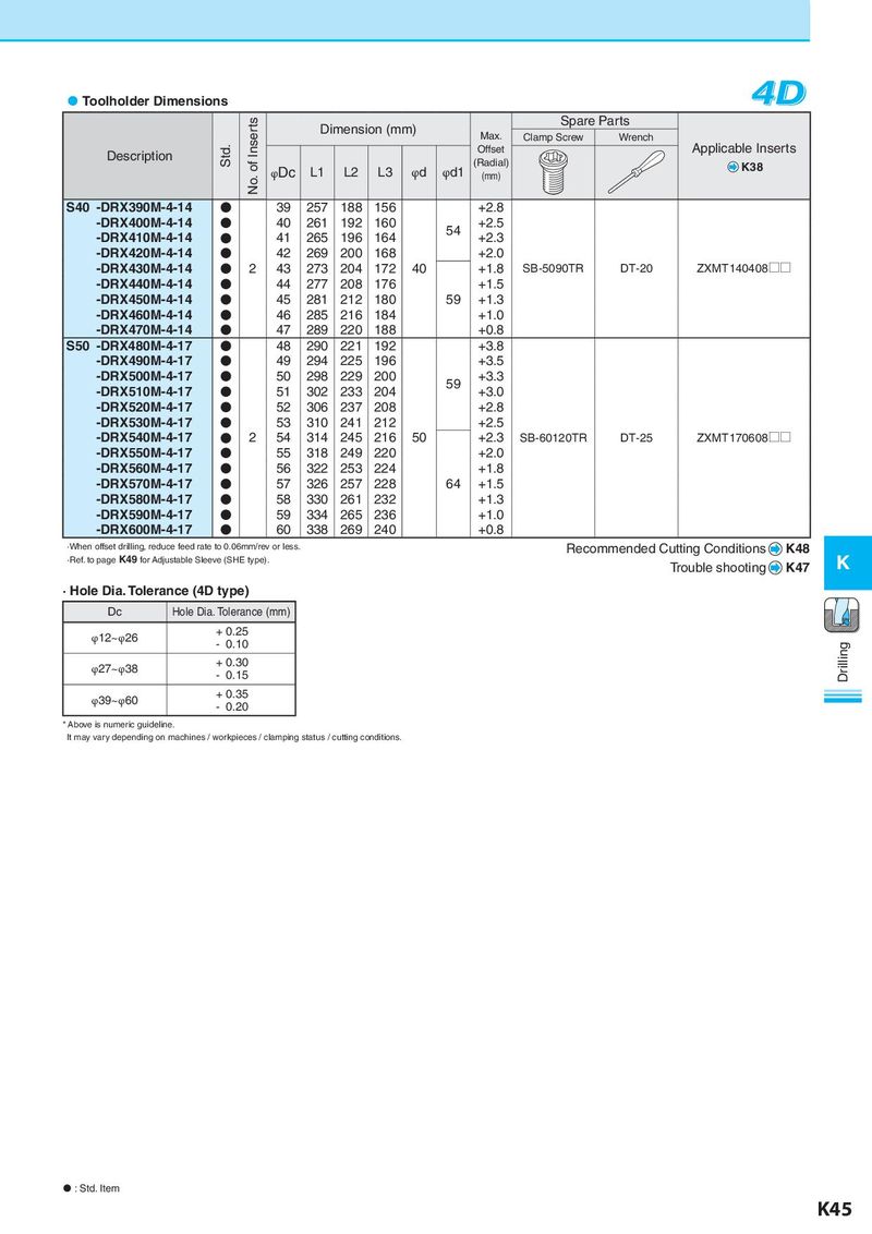
Toolholder Dimensions 4D No. of Inserts Dimension (mm) Spare Parts Max. Clamp Screw Wrench Description Std. Offset Applicable Inserts φDc L1 L2 L3 φd φd1 (Radial) K38 (mm) S40 -DRX390M-4-14 ● 39 257 188 156 +2.8 -DRX400M-4-14 ● 40 261 192 160 54 +2.5 -DRX410M-4-14 ● 41 265 196 164 +2.3 -DRX420M-4-14 ● 42 269 200 168 +2.0 -DRX430M-4-14 ● 2 43 273 204 172 40 +1.8 SB-5090TR DT-20 ZXMT140408 U U -DRX440M-4-14 ● 44 277 208 176 +1.5 -DRX450M-4-14 ● 45 281 212 180 59 +1.3 -DRX460M-4-14 ● 46 285 216 184 +1.0 -DRX470M-4-14 ● 47 289 220 188 +0.8 S50 -DRX480M-4-17 ● 48 290 221 192 +3.8 -DRX490M-4-17 ● 49 294 225 196 +3.5 -DRX500M-4-17 ● 50 298 229 200 59 +3.3 -DRX510M-4-17 ● 51 302 233 204 +3.0 -DRX520M-4-17 ● 52 306 237 208 +2.8 -DRX530M-4-17 ● 53 310 241 212 +2.5 -DRX540M-4-17 ● 2 54 314 245 216 50 +2.3 SB-60120TR DT-25 ZXMT170608 U U -DRX550M-4-17 ● 55 318 249 220 +2.0 -DRX560M-4-17 ● 56 322 253 224 +1.8 -DRX570M-4-17 ● 57 326 257 228 64 +1.5 -DRX580M-4-17 ● 58 330 261 232 +1.3 -DRX590M-4-17 ● 59 334 265 236 +1.0 -DRX600M-4-17 ● 60 338 269 240 +0.8 ·When offset drilling, reduce feed rate to 0.06mm/rev or less. Recommended Cutting Conditions K48 ·Ref. to page K49 for Adjustable Sleeve (SHE type). Trouble shooting K47 K · Hole Dia. Tolerance (4D type) Dc Hole Dia. Tolerance (mm) φ12~φ26 + 0.25 - 0.10 Drilling φ27~φ38 + 0.30 - 0.15 φ39~φ60 + 0.35 - 0.20 * Above is numeric guideline. It may vary depending on machines / workpieces / clamping status / cutting conditions. : Std. Item K45