Основной каталог Kyocera 2016-2017 - страница 513
Навигация
 Каталог Kyocera фрезы MFH для высокоскоростной обработки
 Каталог Kyocera фрезы MEC высокопроизводительные концевые и торцевые фрезы
 Каталог микроинструмента Kyocera 2015-2016
 Каталог Kyocera высокоэффективные сверла со сменными пластинами DRV
 Каталог Kyocera пластины TQ для нарезания резьбы c прессованным стружколомом
 Каталог Kyocera высокопроизводительные модульные сверла DRA
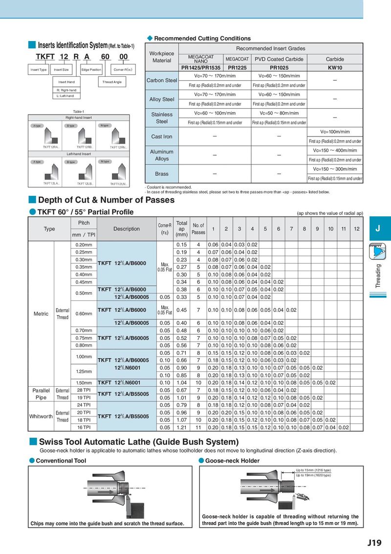
■ Inserts Identification System (Ref. toTable-1) ◆ Recommended Cutting Conditions
Recommended Insert Grades
TKFT 12 R A 60 00 Workpiece MEGACOAT
Material NANO MEGACOAT PVD Coated Carbide Carbide
Insert Type Insert Size Edge Position Corner-R(rH) PR1425/PR1535 PR1225 PR1025 KW10
Vc=70 ~ 170m/mim Vc=60 ~ 150m/mim
Insert Hand Thread Angle Carbon Steel First ap (Radial):0.2mm and under First ap (Radial):0.2mm and under -
R: Right-hand
L: Left-hand Vc=70 ~ 170m/mim Vc=60 ~ 150m/mim
Alloy Steel First ap (Radial):0.2mm and under First ap (Radial):0.2mm and under -
Table-1 Stainless Vc=60 ~ 100m/mim Vc=50 ~ 80m/mim
Right-hand Insert Steel -
A type B type N type First ap (Radial):0.15mm and under First ap (Radial):0.15mm and under
Vc=100m/mim
Cast Iron - - First ap (Radial):0.2mm and under
TKFT12RA.. TKFT12RB.. TKFT12RN.. Vc=150 ~ 400m/mim
Left-hand Insert Aluminum - -
A type B type N type Alloys First ap (Radial):0.2mm and under
Vc=150 ~ 300m/mim
Brass - - First ap (Radial):0.15mm and under
TKFT12LA.. TKFT12LB.. TKFT12LN..
· Coolant is recommended.
· In case of threading stainless steel, please set two to three passes more than